Cylinder block for hydraulic plunger pump

A technology of hydraulic plunger pump and cylinder block, which is applied in the field of cylinder block for swash plate type axial plunger pump, can solve the problems of reducing the comprehensive quality of parts, reducing the performance of parts, reducing the stability of use, etc., and achieves simplified working conditions. , Improve the service life and reduce the effect of friction

Inactive Publication Date: 2017-04-05
WUXI DEMEIJIA MACHINERY TECH CO LTD
View PDF5 Cites 0 Cited by
  • Summary
  • Abstract
  • Description
  • Claims
  • Application Information

AI Technical Summary

Problems solved by technology

[0002] In the actual processing process of the PVG130 pump cylinder block of American Ogail Company, due to the complex structure of the accessories and the large number of parts, it leads to many processing procedures and makes the processing cost expensive. Because of the large number of parts, during the processing The overall quality of all parts is reduced; moreover, in the process of use, because of the large number of parts, the friction pairs of the parts become more complicated, and the working conditions become more complicated, which will increase the wear and tear of the parts and reduce the performance of the parts, thus causing the failure of the whole pump. Decreased usage stability

Method used


Image

  • Cylinder block for hydraulic plunger pump
  • Cylinder block for hydraulic plunger pump
  • Cylinder block for hydraulic plunger pump

Examples


Embodiment Construction

[0017] The present invention will be further described below in conjunction with the accompanying drawings and embodiments.

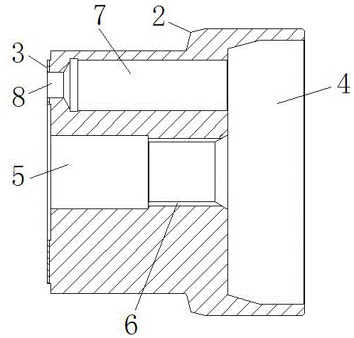
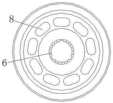
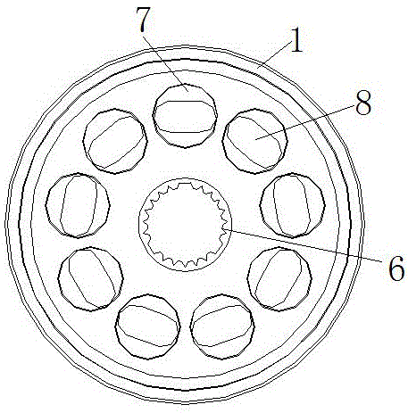
[0018] Such as figure 1 , figure 2 and image 3 As shown, a cylinder block for a hydraulic plunger pump according to the present invention includes a cylinder body 1, and the cylinder body 1 is composed of a steel base layer 2 and a copper base layer 3, which are fixedly connected, and the copper base layer The base layer 3 is arranged on the end face of the cylinder body 1 at the end where the cylinder body 1 is matched with the valve plate, the end face of the copper base layer 3 is a plane, and a stepped hole 4 is provided at the other end of the cylinder body 1 A through hole 5 is provided in the middle of the cylinder body 1, and the through hole 5 extends from the end of the cylinder body 1 where the copper matrix layer 3 is provided to the stepped hole 4, and the through hole 5 near the stepped hole 4 The end of the hole 5 is provided with an...


PUM

PropertyMeasurementUnit
Thicknessaaaaaaaaaa

Abstract

The invention relates to a cylinder block for a hydraulic plunger pump. The cylinder block comprises a cylinder block body; the cylinder block body comprises a steel substrate layer and a copper substrate layer which are fixedly connected with each other; the copper substrate layer is arranged on the end surface of one end, matched with a valve plate, of the cylinder block body; the end surface of the copper substrate layer is a plane; a stepped hole is formed in the other end of the cylinder block body; a through hole is formed in the middle of the cylinder block body and extends from the end, where the copper substrate layer is arranged, of the cylinder block body to the stepped hole; an internal spline is arranged at one end, close to the stepped hole, of the through hole; plunger holes are formed in the peripheral side of the through hole along the through hole at intervals; flow channels are formed in bottoms of the plunger holes; one end of each plunger hole is connected with the stepped hole; and each flow channel extends to the end surface of one end of the cylinder block body. According to the cylinder block, the friction coefficient is low, the bearing capacity is large, the cost is reduced, stable running is realized, and the service life of the whole machine is prolonged.

Description

technical field [0001] The invention relates to a hydraulic plunger pump accessory, in particular to a cylinder block for a swash plate type axial plunger pump. Background technique [0002] In the actual processing process of the PVG130 pump cylinder block of American Ogail Company, due to the complex structure of the accessories and the large number of parts, it leads to many processing procedures and makes the processing cost expensive. Because of the large number of parts, during the processing The overall quality of all parts is reduced; moreover, in the process of use, because of the large number of parts, the friction pairs of the parts become more complicated, and the working conditions become more complicated, which will increase the wear and tear of the parts and reduce the performance of the parts, thus causing the failure of the whole pump. Reduced usage stability. Contents of the invention [0003] Purpose of the invention: The purpose of the invention is to ...

Claims


Application Information

Patent Timeline
IPC IPC(8): F04B53/16
Inventor 孙晓浩刘琴
Owner WUXI DEMEIJIA MACHINERY TECH CO LTD
Why Eureka
Try Eureka