
Treatment method for slab retention in slab continuous casting

A processing method and slab continuous casting technology, which is applied in the field of slab continuous casting stagnant slab processing, can solve problems such as increased resistance to casting, failure of driving rollers, and failure to achieve the effect of casting, so as to reduce the resistance of casting , Guaranteed pulling out, time-saving effect

Active Publication Date: 2017-04-05
SHANGHAI MEISHAN IRON & STEEL CO LTD
View PDF6 Cites 15 Cited by
  • Summary
  • Abstract
  • Description
  • Claims
  • Application Information

AI Technical Summary

Problems solved by technology

Therefore, the method announced in the plan according to the casting speed and the method of water distribution during the process of stagnant billet processing has great limitations and disadvantages
In addition, the lifting and pressing methods of the sectors announced do not carry out differential control and pressure setting for the pressing and lifting of the drive rollers of the sectors during the processing process, which will inevitably cause the sectors in front of the continuous casting machine (such as 1 #2#3# section) driving rollers not only can’t play the role of drawing in the drawing process, but will cause the increase of drawing resistance, which is not conducive to the smooth drawing of the slab
Another disadvantage is that, since the frictional resistances of the drive rollers of each sector are completely different during the process of processing stagnant billets, if all the drive rollers of the sector are involved in the drawing control without considering the difference, it will be There is a high probability that the drive roller drive handle will break when processing stagnant billets, and abnormal conditions such as drive roller failure will occur.

Method used


Image

  • Treatment method for slab retention in slab continuous casting
  • Treatment method for slab retention in slab continuous casting
  • Treatment method for slab retention in slab continuous casting

Examples


Embodiment 1

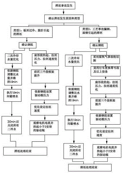
[0034] A slab continuous casting stagnant slab treatment method, the method is implemented according to the following steps:

[0035] First of all, determine the types and causes of stagnant billet. According to the current situation of stagnant billet that has occurred in slab continuous casting machines at home and abroad, it can be roughly divided into two categories: (1) Continuous casting caused by equipment failure and operational reasons The machine has a long downtime, and the slab is stagnant due to overcooling of the slab, or the local thickness of the slab exceeds the set value caused by the failure of the process, continuous casting cooling, and hydraulic equipment; (2) The continuous casting machine has abnormal process accidents , such as breakout and overflow of steel, resulting in cold steel jamming or stagnation caused by bonding between slabs and other equipment of the casting machine;

[0036] 1. Long downtime of continuous casting machine caused by equipmen...


PUM


Abstract

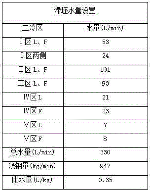
The invention relates to a treatment method for slab retention in slab continuous casting. The treatment method is characterized by comprising the following steps: firstly, confirming slab retention reasons divided into two kinds according to all slab retention conditions suffered by domestic and abroad slab continuous casting machines at present: 1) long continuous casting machine downtime caused by equipment faults and operation reasons, slab retention caused by slab supercooling or slab retention resulted from the condition that the local thickness of a slab exceeds a set value because process, continuous casting cooling and hydraulic equipment faults appear; and 2) slab retention resulted from cold steel jamming and bonding of the slab and other equipment of the casting machine because the continuous casting machine suffers from process abnormity accidents including steel leakage and steel overflow; and next, adopting an optimal control method for different streamline secondary cooling water quantities, an optimizing method for different sector section lifting and slab drawing pressure and speed settings and a cutting method for accidents with different coal gas-to-oxygen ratios according to the different reasons.

Description

technical field [0001] The invention relates to a method for treating stagnant slabs in continuous casting of slabs, belonging to the technical field of continuous casting of iron and steel metallurgy. Background technique [0002] In the current metallurgical enterprises, most slab continuous casting machines mainly include main equipment such as mold, 0# section, sector section, straightening section and horizontal section. During the production process of slab continuous casting, there will be production accidents in which the slab cannot be pulled out smoothly in the continuous casting machine due to hydraulic system failure, transmission system failure, or other production accidents. For "stagnant blank". Continuous casting stagnation is a major production accident in the continuous casting production process. After the stagnation occurs, the production will be stopped for several hours or even dozens of hours, which will seriously affect the output of the continuous c...

Claims


Application Information

Patent Timeline
IPC IPC(8): B22D11/126B22D11/12
Inventor 邹世文
Owner SHANGHAI MEISHAN IRON & STEEL CO LTD
Learn More