
Variable-frequency centrifugal rod pipe blanking machine based on hydraulic compensation

A technology of centrifugal rod and material machine, which is applied in the field of frequency conversion centrifugal rod tube material cutting machine, which can solve the problems of uneven sharpness of sawtooth due to feed change, waste of raw materials, broken belt, etc.

Inactive Publication Date: 2017-04-05
CHINA UNIV OF PETROLEUM (EAST CHINA)
View PDF6 Cites 8 Cited by
  • Summary
  • Abstract
  • Description
  • Claims
  • Application Information

AI Technical Summary

Problems solved by technology

Although the section of the bar produced by these blanking methods is flat and the verticality is high, it is necessary to increase the chamfering process, the blanking efficiency is low, the required blanking force is large, and the waste of raw materials is serious.
Due to the different size and material of the bar to be cut, the linear speed of the saw band, the change of the feed rate and the unevenness of the sharpness of the saw teeth, the phenomenon of broken teeth and broken belts is also a major drawback, so it cannot meet the requirements of green manufacturing.
[0004] At present, there is no precision blanking machine based on low-stress blanking technology widely used in industrialization in the society. The purpose of this invention is to invent a rod and tube material blanking machine that can realize industrial application

Method used


Image

  • Variable-frequency centrifugal rod pipe blanking machine based on hydraulic compensation
  • Variable-frequency centrifugal rod pipe blanking machine based on hydraulic compensation
  • Variable-frequency centrifugal rod pipe blanking machine based on hydraulic compensation

Examples


Embodiment

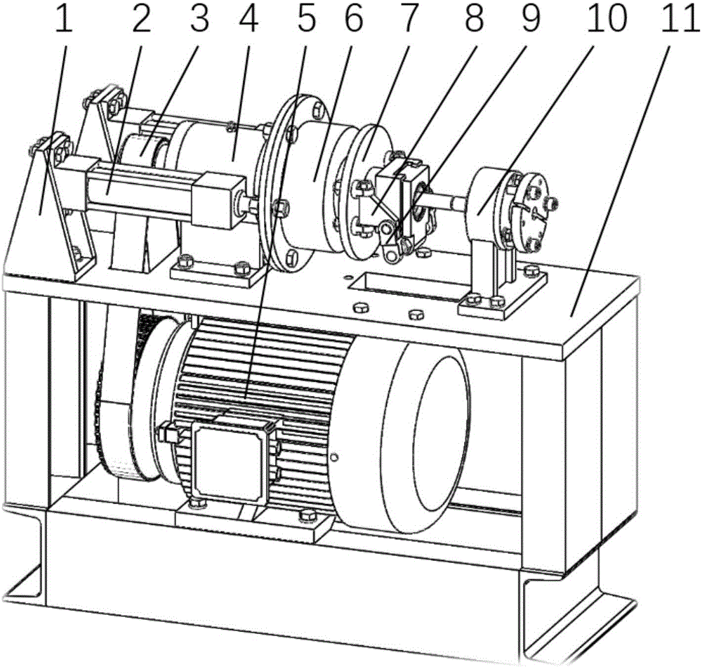
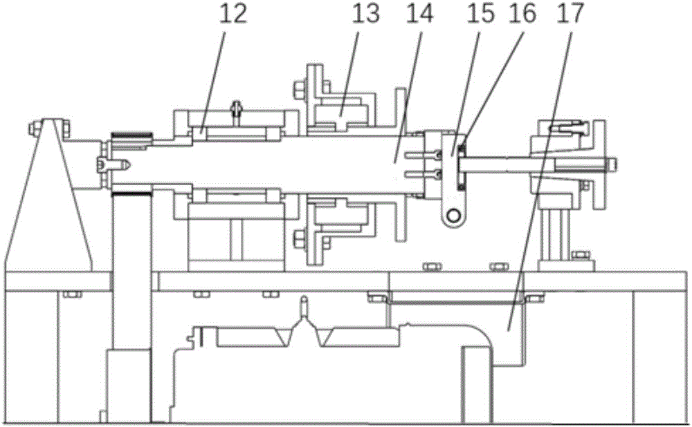
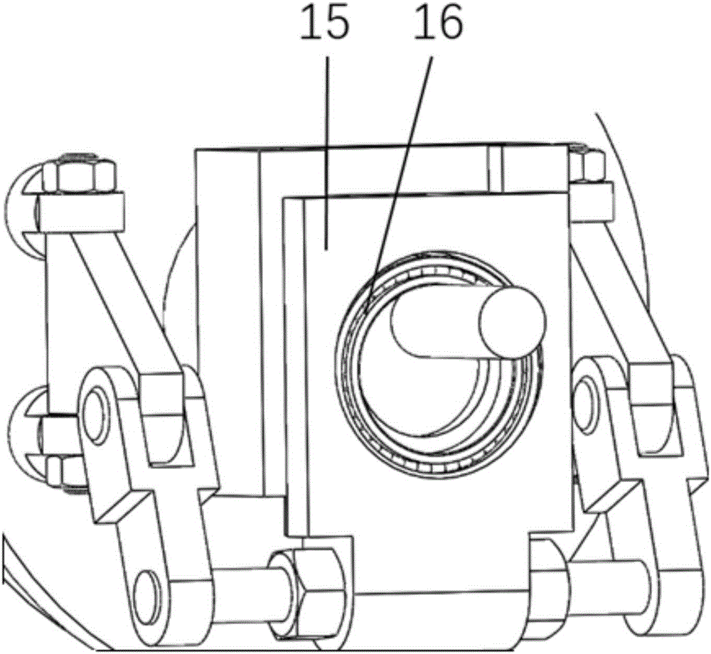
[0017] like figure 1 , figure 2 , image 3 As shown, the hydraulic compensation-based variable frequency centrifugal rod pipe blanking machine in the embodiment of the present invention includes a hydraulic cylinder support 1, a hydraulic cylinder 2, a timing belt 3, a fixed bearing box 4, a three-phase AC motor 5, and a sliding bearing box 6 , Rotating push plate 7, triangular block 8, connecting block 9, bar clamp 10, frame 11, deep groove ball bearing 12, two-way thrust ball bearing 13, main shaft 14, slider 15, inner surface with equal interval groove resistance Grinding bearing 16 and material block guide groove 17, the hydraulic cylinder support 1 is installed on one end of the frame 11, and is fixed on the frame 11 with bolts and nuts; the synchronous belt 3 connects the small pulley and the large pulley, so The small pulley is fixed on the main shaft 14, and the large pulley is fixed on the output shaft of the three-phase AC motor 5; The deep groove ball bearing 12...


PUM


Abstract

The invention relates to a variable-frequency centrifugal rod pipe blanking machine based on hydraulic compensation. The machine comprises a hydraulic cylinder bracket, a hydraulic cylinder, a synchronous belt, a fixed bearing box, a three-phase alternating-current motor, a slide bearing box, a rotating push disc, a triangular block, a connecting block, a rod fixture, a frame, a deep groove ball bearing, a two-way thrust ball bearing, a main shaft, a slide block, a wear resistant bearing with grooves on the inner surface at equal intervals, and a material block guide groove. The machine precisely blanks rod pipes by fully using hydraulic compensation, the centrifugal effect and the stress concentration effect based on a low-stress blanking technology. During blanking, sharp annular V-shaped grooves are formed in the peripheries of the surfaces of metal rod pipes beforehand; and then, the rod pipes are peripherally extruded by using the rotating centrifugal force and the hydraulic compensation force. Under the effect of centrifugal force and hydraulic compensation force, cracks are generated in the stress concentration places of the V-shaped groove. According to traditional rupture theoretical knowledge, after the cracks at the tip ends of the V-shaped grooves are generated, the cracks can quickly expand along the radial surfaces to totally break finally, so that the blanking is realized.

Description

technical field [0001] The invention relates to a frequency conversion centrifugal rod pipe material cutting machine based on hydraulic compensation, belonging to the field of precision cutting. Background technique [0002] In the metal products and machinery manufacturing industry, blanking is the first process of metal forming processing, which is widely used in the preparation process of die forging, cold extrusion, metal chain pins, bolts, rolling bearing rollers, auto parts production, etc. . At present, the annual domestic demand for precision cutting of bars reaches tens of millions of tons, the annual demand for motorcycle chains alone reaches 80 million meters, and the demand for internal combustion engine piston pins reaches 20 million. At present, the cutting method used in industrial production is to directly cut the round bar and tube material with a common die, or use a high-speed band saw to cut the round bar and tube material. These methods often cause cutt...

Claims


Application Information

Patent Timeline
IPC IPC(8): B21D28/00
CPCB21D28/00
Inventor 张立军周数恩张德培王晓强王旱祥刘延鑫
Owner CHINA UNIV OF PETROLEUM (EAST CHINA)
Learn More