
Tricyclic vacuum arc thruster

A thruster and vacuum arc technology, which is applied to aircrafts, aerospace vehicles, and propulsion system devices of aerospace vehicles, etc., can solve the problems of short thruster life, small cathode ablation area, large plume divergence angle, etc. The effect of improving performance and life

Active Publication Date: 2017-03-29
LANZHOU INST OF PHYSICS CHINESE ACADEMY OF SPACE TECH
View PDF5 Cites 5 Cited by
  • Summary
  • Abstract
  • Description
  • Claims
  • Application Information

AI Technical Summary

Problems solved by technology

The current single-cathode and single-anode coaxial vacuum arc thrusters have a small cathode ablation area, resulting in a short service life and low reliability of the thruster. At the same time, the divergence angle of the plume is large due to the space charge effect, which affects the thruster. performance

Method used


Image

  • Tricyclic vacuum arc thruster
  • Tricyclic vacuum arc thruster
  • Tricyclic vacuum arc thruster

Examples


Embodiment 1

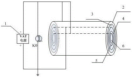
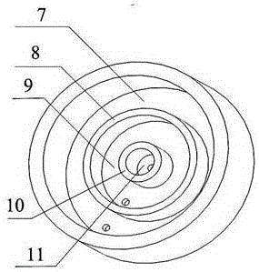
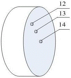
[0012] Embodiment 1, with reference to figure 1 , 2 , 3, a three-ring vacuum arc thruster, the thruster includes a cylindrical cathode 6 placed in the center (the cylindrical cathode structure is conducive to the uniform ablation of the cathode material, thereby prolonging the life of the thruster), the cylindrical cathode 6. The insulator II5, the common anode 4, the insulator I3 and the outer ring cathode 2 are arranged concentrically on the outer periphery in turn; the cylindrical cathode 6, the insulator II5, the common anode 4, the insulator I3 and the outer ring cathode 2 are sequentially installed on the installation base The cylindrical cathode installation groove 11, the insulator II installation seat 10, the common anode installation groove 9, the insulator I installation seat 8 and the outer ring cathode installation groove 7; the cylindrical cathode installation groove 11, the common anode installation groove 9 , Outer ring cathode installation groove 7 three equa...

Embodiment 2

[0013] Embodiment 2. On the basis of Embodiment 1, insulating rings and cathode rings are sequentially added to form a vacuum arc thruster with a multi-ring structure as required, so as to expand the power of the thruster and expand the application range of the thruster.

[0014] When the thruster is working, the voltage peak generated by the power processing unit simultaneously breaks down the metal conductive films on the end faces of the two insulators, and induces the main discharge between the cathode and anode of the two groups. The resulting plasma ions are accelerated by mechanisms such as aerodynamics and electron-ion friction to generate thrust.


PUM


Abstract

The invention discloses a tricycle vacuum arc thruster. The thruster comprises a cylindrical cathode arranged in the center. An insulator II, a common anode, an insulator I and an outer ring cathode are sequentially and concentrically arranged on the periphery of the cylindrical cathode. The cylindrical cathode, the insulator II, the common anode, the insulator I and the outer ring cathode are sequentially arranged in a cylindrical cathode installation groove, an insulator II installation base, a common anode installation groove, an insulator I installation base and an outer ring cathode installation groove of an installation base. A cylindrical cathode binding post, a common anode binding post and an outer ring cathode binding post are sequentially arranged on the outer end face of the installation base from the center to the outer side. The cathode binding post and the outer ring cathode binding post are connected to the negative electrode of a power source, and the common anode binding post is connected to the positive electrode of the power source. The end face, located in the installation base, of the insulator I and the end face, located in the installation base, of the insulator II are plated with metal conductive films. The efficiency of the thruster is improved, and the service life of the thruster is prolonged.

Description

technical field [0001] The invention relates to a three-ring vacuum arc thruster used in space, belonging to the technical field of spacecraft propulsion. Background technique [0002] In recent years, satellites have been developing in the direction of low cost and distributed. Micro-nano satellites have the advantages of low cost, short development cycle, strong expansion capability, and flexible launch methods. Micro-nano satellites have important application prospects and strategic significance for both civilian and military applications. The rapid development of micro-satellites and micro-nano-satellites has put forward high requirements for advancement. The vacuum arc thruster (VAT) has become an ideal type of electric propulsion for micro-nano satellites due to its advantages of small mass, high specific impulse, and simple structure. Micro-propulsion can mainly meet the propulsion needs of micro-nano satellites, mainly including: (1) damping compensation, orbit ele...

Claims


Application Information

Patent Timeline
Patent Type & Authority Applications(China)
IPC IPC(8): B64G1/40
CPCB64G1/405F03H1/0087
Inventor 吴先明张天平任亮吴辰宸李啸天贾艳辉王尚民
Owner LANZHOU INST OF PHYSICS CHINESE ACADEMY OF SPACE TECH
Learn More