
Hydraulic actuator and method for operating a hydraulic actuator

A technology of hydraulic actuators and piezoelectric actuators, applied in fluid pressure actuators, piezoelectric effect/electrostrictive or magnetostrictive motors, generators/motors, etc., can solve the problem of high actuators Stiffness and other issues

Active Publication Date: 2017-03-22
METISMOTION GMBH
View PDF6 Cites 3 Cited by
  • Summary
  • Abstract
  • Description
  • Claims
  • Application Information

AI Technical Summary

Problems solved by technology

However, the actuators used to date have high stiffness

Method used


Image

  • Hydraulic actuator and method for operating a hydraulic actuator
  • Hydraulic actuator and method for operating a hydraulic actuator

Examples


Embodiment Construction

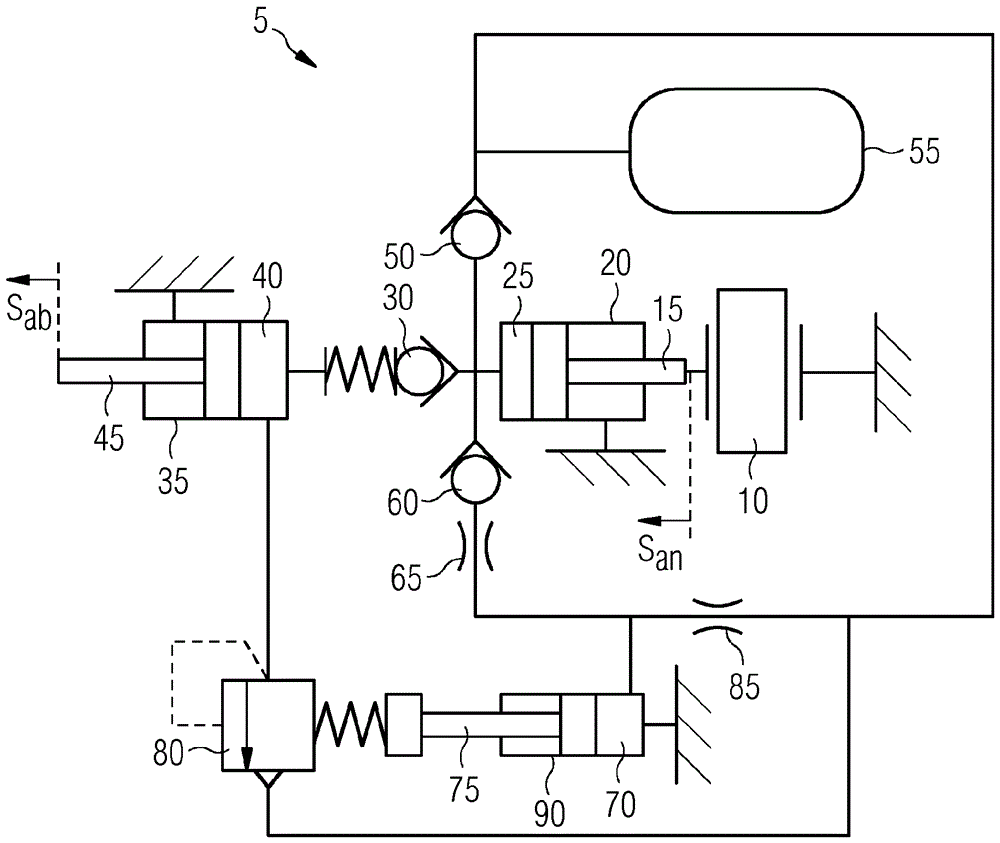
[0019] figure 1 The illustrated hydraulic actuator 5 according to the invention comprises a piezoelectric actuator 10 kinematically coupled to a drive piston 15 of a hydraulic drive cylinder 20 .

[0020] The drive cylinder 20 comprises a hydraulic drive volume 25 filled with hydraulic oil in a manner known per se. This drive volume 25 is hydraulically coupled to a hydraulic output cylinder 35 via a check valve 30 in order to open when a sufficiently high opening pressure exists. The non-return valve 30 is correspondingly prestressed. On the drive side, the output cylinder 35 has an output volume 40 which moves an output piston 45 on the output side.

[0021] Furthermore, the drive volume is coupled via a check valve 50 to a reservoir 55 so that the drive volume can be supplied to this reservoir.

[0022] Furthermore, the drive volume 25 can be supplied to the prestressing volume 70 of the hydraulic prestressing cylinder 90 via the nonreturn valve 60 and the throttle valve ...


PUM


Abstract

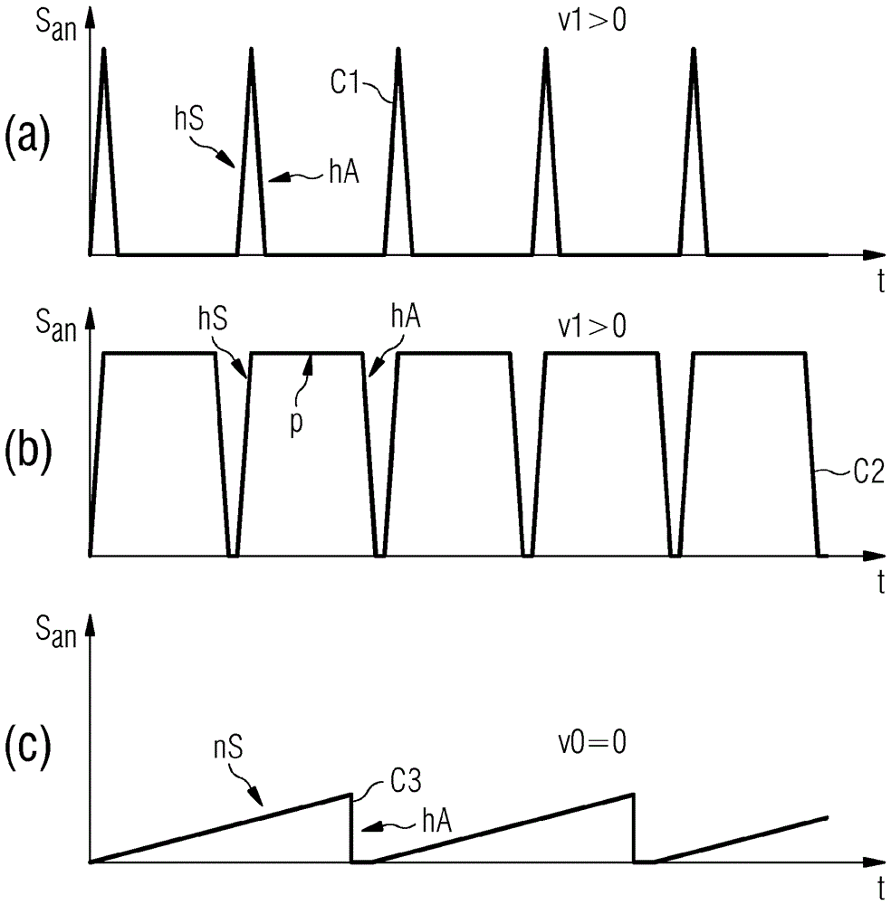
The hydraulic actuator comprises: a hydraulic input cylinder having an input piston; a hydraulic output cylinder, which is hydraulically coupled to the input cylinder; and a pressure-limiting valve, which limits the output cylinder with respect to pressure in dependence on the usability of a force on the input piston. The method is a method for operating such a hydraulic actuator, wherein the drive actuator is deflected with deflections having a deflection duration at a deflection frequency for the duration of an acting or a non-acting phase of the hydraulic actuator, wherein the deflection duration defines a movement stiffness of the hydraulic actuator and the deflection frequency defines the resulting deflection speed of the hydraulic actuator.

Description

technical field [0001] The invention relates to a hydraulic actuator and a method for operating a hydraulic actuator. Background technique [0002] Greater flexibility in conventional machine automation is expected, for example, within the framework of "Industry 4.0". So-called "soft robotics" have become increasingly important in recent times. Manufacturing robots are intended to work directly with humans during the soft machine process. Actuators with variable stiffness and low mass are required for this. The model for such an actuator is a human muscle, which can be prestressed and thus stiffened depending on the application. However, the muscles are not prestressed under normal conditions, so that in the event of a collision with a rigid object, the forces acting on the body and thus the risk of injury are minimized. However, the actuators used so far have high stiffness. In order to avoid the occurrence of a collision, sensors are additionally used which detect obs...

Claims


Application Information

Patent Timeline
Patent Type & Authority Applications(China)
IPC IPC(8): F15B7/08F15B13/02
CPCF15B7/08F15B13/024H02N2/043F15B13/0401F15B1/26F15B15/149
Inventor G.巴赫迈尔A.格德克T.冯茨W.策尔斯
Owner METISMOTION GMBH
Learn More