
Loudspeaker assembly, loudspeaker box and mobile terminal

A mobile terminal and speaker technology, which is applied in the field of speaker components, speakers and mobile terminals, can solve the problems of squeezed audio space, poor low-frequency sound reproduction effect, and small speaker sound, so as to increase expressive ability, improve effect, and make music sound pleasant Effect

Active Publication Date: 2017-03-22
NUBIA TECHNOLOGY CO LTD
View PDF8 Cites 11 Cited by
  • Summary
  • Abstract
  • Description
  • Claims
  • Application Information

AI Technical Summary

Problems solved by technology

[0002] As people have higher and higher requirements for the portability, ultra-thin and ultra-light of mobile terminals, the thickness of mobile terminals is getting thinner and more functions, which virtually squeezes the audio space of mobile terminals, resulting in mobile The loudspeaker of the terminal has a small sound and the effect of restoring low-frequency sound is poor, so the poor audio playback effect of the mobile terminal has become a pain point in use
[0003] Existing mobile terminal speaker components such as Figure 3-4 As shown, it includes a speaker unit and a sound cavity body unit, wherein the speaker unit includes a diaphragm 1, a coil 2, a magnetic steel 3 and a magnetic frame 4, and the sound cavity body unit and the diaphragm 1 of the speaker unit together form a sealed rear Sound cavity 5, based on the existing loudspeaker assembly, the method for improving the playing effect of the external high-frequency sound of the mobile terminal is usually by improving the function of the speaker and replacing a larger speaker; improving the external low-frequency sound of the mobile terminal. The method of playing the effect is usually to increase the cavity volume of the sound cavity cavity unit or fill the sound-absorbing cotton, and the above-mentioned method is contrary to the trend of ultra-thin and light-weight mobile terminals

Method used


Image

  • Loudspeaker assembly, loudspeaker box and mobile terminal
  • Loudspeaker assembly, loudspeaker box and mobile terminal
  • Loudspeaker assembly, loudspeaker box and mobile terminal

Examples


Embodiment Construction

[0045] It should be understood that the specific embodiments described here are only used to explain the present invention, not to limit the present invention.

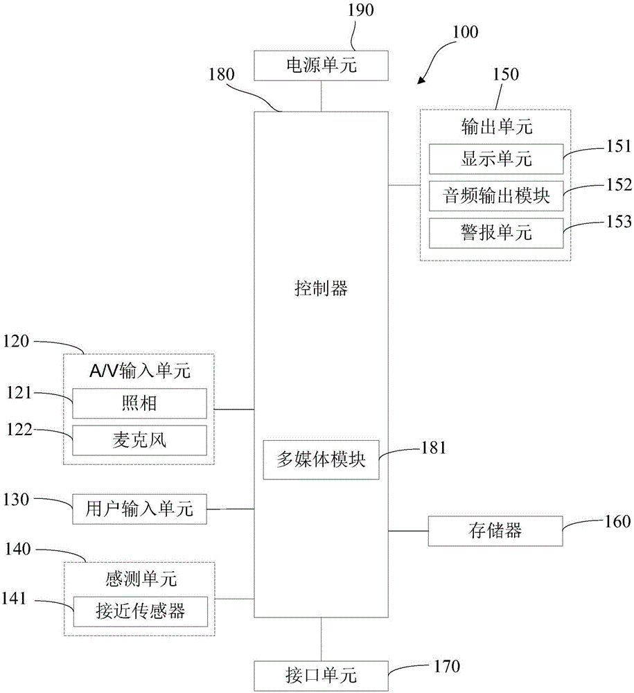
[0046] A mobile terminal implementing various embodiments of the present invention will now be described with reference to the accompanying drawings. In the following description, use of suffixes such as 'module', 'part' or 'unit' for denoting elements is only for facilitating description of the present invention and has no specific meaning by itself. Therefore, "module" and "component" may be used mixedly.

[0047] Mobile terminals may be implemented in various forms. For example, terminals described in the present invention may include devices such as mobile phones, smart phones, notebook computers, digital broadcast receivers, PDAs (Personal Digital Assistants), PADs (Tablet Computers), PMPs (Portable Multimedia Players), navigation devices, etc. mobile terminals and fixed terminals such as digital TVs, desktop c...


PUM


Abstract

The invention discloses a loudspeaker assembly, a loudspeaker box and a mobile terminal. The loudspeaker assembly includes a loudspeaker unit, an assistant loudspeaker unit, and a sound chamber unit, wherein the loudspeaker unit and the assistant loudspeaker unit share a rear chamber provided by the sound chamber unit. The low-frequency loudness of the sound played by the loudspeaker unit is enhanced by the simultaneous reverse-direction vibration of the diaphragm of the loudspeaker unit and the diaphragm of the assistant loudspeaker unit. The low-frequency loudness of the sound played by the loudspeaker unit is reduced by the simultaneous same-direction vibration of the diaphragm of the loudspeaker unit and the diaphragm of the assistant loudspeaker unit. Compared with the prior art, the loudspeaker assembly increases the low-frequency loudness of the audio output by the loudspeaker, and can greatly reduce the low-frequency loudness in a specific application scene so as to be suitable for high-frequency output. The loudspeaker assembly is particularly suitable for highly integrated or smaller and smaller mobile terminals, which helps to reduce the volume of the mobile terminal while enhancing the audio quality.

Description

technical field [0001] The invention relates to the field of mobile terminal control, in particular to a loudspeaker assembly, a sound box and a mobile terminal. Background technique [0002] As people have higher and higher requirements for the portability, ultra-thin and ultra-light of mobile terminals, the thickness of mobile terminals is getting thinner and more functions, which virtually squeezes the audio space of mobile terminals, resulting in mobile The loudspeaker of the terminal has low sound and poor reproduction effect on low-frequency sound, so the poor audio playback effect of the mobile terminal has become a pain point in use. [0003] Existing mobile terminal speaker components such as Figure 3-4 As shown, it includes a speaker unit and a sound cavity body unit, wherein the speaker unit includes a diaphragm 1, a coil 2, a magnetic steel 3 and a magnetic frame 4, and the sound cavity body unit and the diaphragm 1 of the speaker unit together form a sealed rea...

Claims


Application Information

Patent Timeline
Patent Type & Authority Applications(China)
IPC IPC(8): H04M1/03H04R1/28H04R9/02H04R9/06
CPCH04M1/03H04M1/035H04R1/2834H04R9/02H04R9/06H04R2499/11
Inventor 丁火根
Owner NUBIA TECHNOLOGY CO LTD
Learn More