
Pattern selection method for light source-mask optimization

A pattern and mask technology, applied in the field of pattern selection of light source-mask optimization, can solve problems such as low efficiency and unreliable results, and achieve high accuracy and high light source-mask optimization effect.

Active Publication Date: 2019-09-03
SEMICON MFG INT (SHANGHAI) CORP
View PDF8 Cites 0 Cited by
  • Summary
  • Abstract
  • Description
  • Claims
  • Application Information

AI Technical Summary

Problems solved by technology

However, the selection of test patterns in the prior art usually relies on the skill and experience of SMO users, such a selection method is inefficient and the results are not reliable

Method used


Image

  • Pattern selection method for light source-mask optimization
  • Pattern selection method for light source-mask optimization
  • Pattern selection method for light source-mask optimization

Examples


Embodiment Construction

[0028] In the following description, numerous specific details are given in order to provide a more thorough understanding of the present invention. It will be apparent, however, to one skilled in the art that the present invention may be practiced without one or more of these details. In other examples, some technical features known in the art are not described in order to avoid confusion with the present invention.

[0029] It should be understood that the invention can be embodied in different forms and should not be construed as limited to the embodiments set forth herein. Rather, these embodiments are provided so that this disclosure will be thorough and complete, and will fully convey the scope of the invention to those skilled in the art.

[0030] The terminology used herein is for the purpose of describing particular embodiments only and is not intended to be limiting of the invention. As used herein, the singular forms "a", "an" and "the / the" are intended to include...


PUM


Abstract

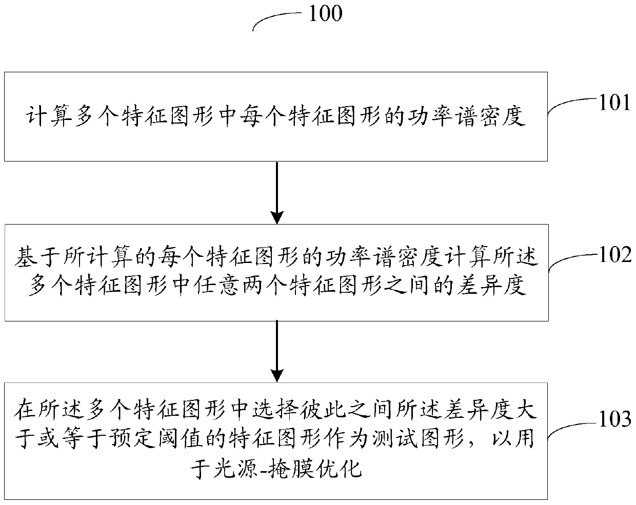
The invention provides a graph selection method used for light source-mask optimization. The graph selection method comprises the steps of calculating power spectrum density of each feature graph in a plurality of feature graphs; calculating a difference degree between any two feature graphs in the feature graphs based on the calculated power spectrum density of each feature graph; and selecting the feature graphs with the difference degree greater than or equal to a predetermined threshold in the feature graphs as test graphs used for the light source-mask optimization. According to the graph selection method used for the light source-mask optimization, provided by the invention, the test graphs used for the light source-mask optimization can be efficiently and quickly selected, and any key graph is not omitted, so that efficient and high-accuracy light source-mask optimization is realized.

Description

technical field [0001] The present invention relates to the field of semiconductor technology, in particular to a pattern selection method for source-mask optimization (SMO). Background technique [0002] As integrated circuits become more complex, feature sizes become smaller. When the feature size of the integrated circuit is close to the system limit of the exposure of the lithography machine, that is, the feature size is close to or smaller than the lithography light source, the layout produced on the silicon wafer will appear obvious distortion. To this end, the lithography system must adopt resolution enhancement (RET) technology to improve the imaging quality. [0003] As technology develops toward smaller critical dimensions, conventional optical proximity correction (Optical Proximity Correction, OPC) that only optimizes the mask may not be able to meet the increasingly stringent critical dimension requirements. In this case, the illumination source / light source c...

Claims


Application Information

Patent Timeline
Patent Type & Authority Patents(China)
IPC IPC(8): G06F17/50
Inventor 裴金花
Owner SEMICON MFG INT (SHANGHAI) CORP
Learn More