
Mining technology for lower slice fully-mechanized coal mining face passing through concentrated coal pillar of higher slice coal seam

A layered fully mechanized mining and coal pillar technology, which is applied to the mining technology field of concentrated coal pillars, can solve problems such as casualties, roof fall or frame pressing, equipment damage, etc., and achieve the effect of improving safety and avoiding roof falling or frame pressing.

Inactive Publication Date: 2017-03-22
CHINA SHENHUA ENERGY CO LTD +1
View PDF6 Cites 2 Cited by
  • Summary
  • Abstract
  • Description
  • Claims
  • Application Information

AI Technical Summary

Problems solved by technology

In terms of roof control, if there is a concentrated coal pillar in the upper layered coal seam, the dynamic load mine pressure usually occurs when the lower layered fully mechanized mining face advances past the upper layered concentrated coal pillar, and the pressure appears very strong. It is also very difficult to control the roof. If the measures are not taken properly, it is very likely that the roof will fall or the frame will be crushed, resulting in equipment damage or casualties, which poses a serious threat to safe production.

Method used


Image

  • Mining technology for lower slice fully-mechanized coal mining face passing through concentrated coal pillar of higher slice coal seam
  • Mining technology for lower slice fully-mechanized coal mining face passing through concentrated coal pillar of higher slice coal seam
  • Mining technology for lower slice fully-mechanized coal mining face passing through concentrated coal pillar of higher slice coal seam

Examples


Embodiment Construction

[0027] The specific implementation manner of the present invention will be further described below in conjunction with the accompanying drawings. Wherein the same components are denoted by the same reference numerals. It should be noted that the words "front", "rear", "left", "right", "upper" and "lower" used in the following description refer to the directions in the drawings, and the words "inner" and "outer ” refer to directions towards or away from the geometric center of a particular part, respectively.

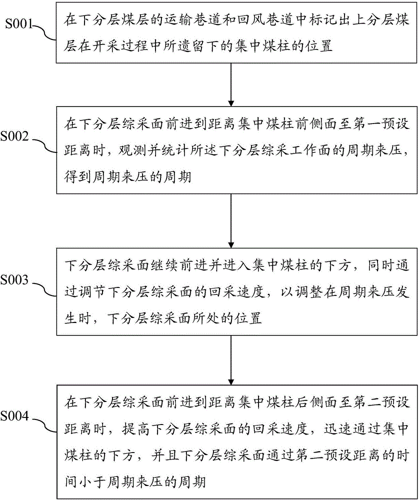
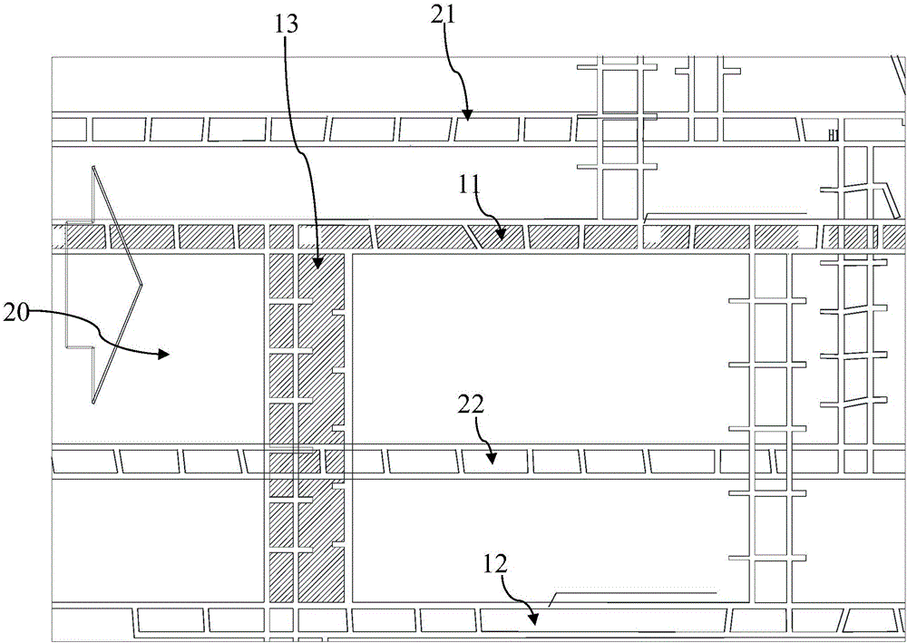
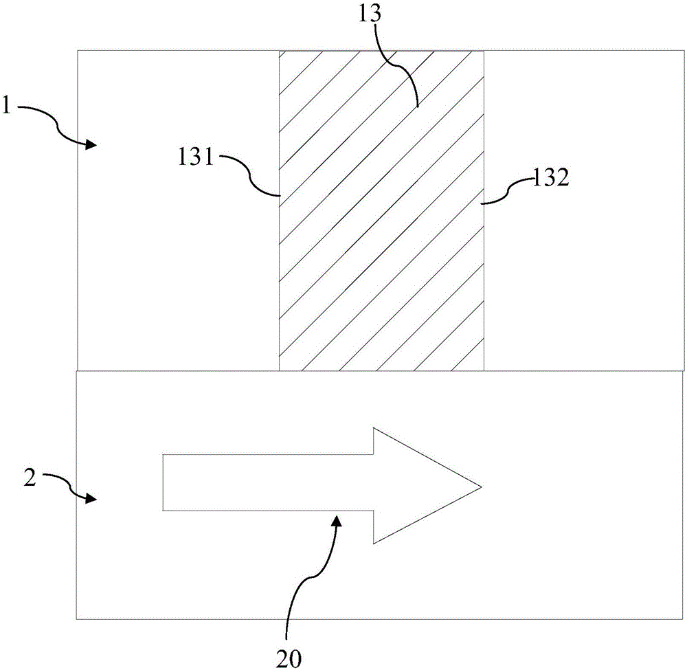
[0028] Such as Figure 1-3 As shown, an embodiment of the present invention provides a mining process for the concentrated coal pillar of the lower layer fully mechanized mining face passing the upper layered coal seam, wherein the coal seam to be mined includes the upper layered coal seam 1 that has been mined and the lower layered layer that is being mined Coal seam 2, comprises the steps:

[0029] S001: mark the exact position of the concentrated coal pillar 13 lef...


PUM


Abstract

The invention discloses a mining technology for a lower slice fully-mechanized coal mining face passing through a concentrated coal pillar of a higher slice coal seam. The mining technology includes the following steps that S001, the position of the concentrated coal pillar is marked in a haulage roadway and a ventilation roadway of a lower slice coal seam; S002, when the lower slice fully-mechanized coal mining face moves forwards to a first preset distance away from the front side face of the coal pillar, observation and statistics of periodic weighting of the lower slice fully-mechanized coal mining face are carried out; S003, by regulating the mining speed of the lower slice fully-mechanized coal mining face, the position of the lower slice fully-mechanized coal mining face is adjusted when periodic weighting occurs; and S004, when the lower slice fully-mechanized coal mining face moves forwards to a second preset distance away from the back side face of the coal pillar, the mining speed of the lower slice fully-mechanized coal mining face is increased, the lower slice fully-mechanized coal mining face rapidly passes through the lower side of the coal pillar, and the time for the lower slice fully-mechanized coal mining face passing through the second preset distance is shorter than the period of periodic weighting. The lower slice fully-mechanized coal mining face can safely pass through the area of the concentrated coal pillar of the higher slice coal seam, roof caving or support crushing is avoided, and the safety of coal production is improved.

Description

technical field [0001] The invention relates to the technical field of coal production, in particular to a mining process for a concentrated coal pillar in which a lower layer fully mechanized mining face crosses an upper layered coal seam. Background technique [0002] Compared with single coal seam mining, coal seam group mining faces greater risks and mining difficulties, especially when mining near the lower coal seam is more difficult. In terms of roof control, if there is a concentrated coal pillar in the upper layered coal seam, the dynamic load mine pressure usually occurs when the lower layered fully mechanized mining face advances past the upper layered concentrated coal pillar, and the pressure appears very strong. It is also very difficult to control the roof. If the measures are not taken properly, it is very likely that the roof will fall or the frame will be crushed, resulting in equipment damage or casualties, which poses a serious threat to safe production. ...

Claims


Application Information

Patent Timeline
IPC IPC(8): E21C41/18
CPCE21C41/18
Inventor 陈苏社许家林朱卫兵鞠金峰薛刚李瑞群
Owner CHINA SHENHUA ENERGY CO LTD
Learn More