
Super-energy-saving air jet loom and utilization method thereof

An air-jet loom, ultra-energy-saving technology, applied in looms, textiles, textiles and papermaking, etc., can solve the problems of unstable air pressure, increased temperature of compressed gas, fabric defects, etc., to save energy and reduce consumption. Effect

Inactive Publication Date: 2017-03-22
QINGDAO TONGCHUN ELECTROMECHANICAL TECH
View PDF14 Cites 1 Cited by
  • Summary
  • Abstract
  • Description
  • Claims
  • Application Information

AI Technical Summary

Problems solved by technology

[0004] Since the independent air supply air jet loom operates without lubrication, the sealing ring is very easy to wear, resulting in unstable compressed air pressure. At the same time, due to high temperature caused by friction, the compressed air temperature rises and the air pressure is unstable, so start 1 - After 2 hours, the air pressure fluctuates greatly, which leads to very obvious fabric defects. This model is an industry-eliminated model;
[0005] Centralized air-supply air-jet looms still need to be improved in the field of air consumption technical indicators. The auxiliary air-jet bags of the existing centralized air-supply air-jet looms are all integrated. Auxiliary injection pressure balance, can not be adjusted separately, the waste of gas is very serious
At the same time, the connection mode of the main spray is: the long spray path is distributed on the fixed main spray and the swing main spray. In most cases, the fixed main spray does not need the assistance of the long spray path, resulting in gas waste of the fixed main spray under normal working conditions.

Method used


Image

  • Super-energy-saving air jet loom and utilization method thereof
  • Super-energy-saving air jet loom and utilization method thereof

Examples


Embodiment Construction

[0034] The present invention is described in detail below in conjunction with accompanying drawing:

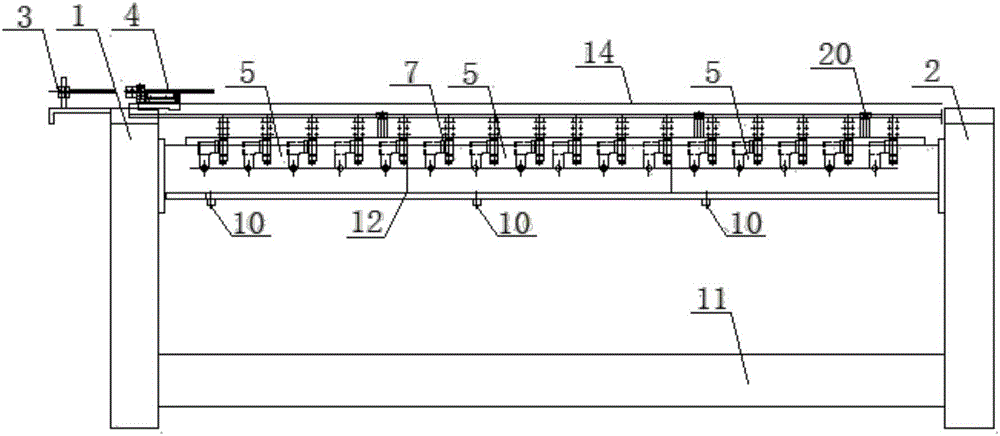
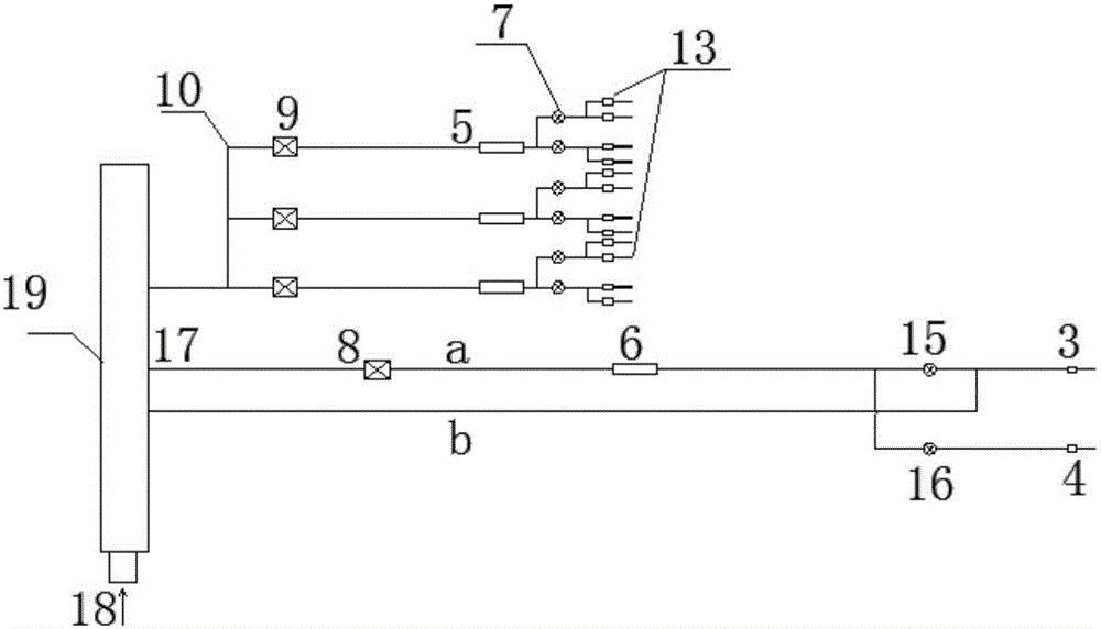
[0035] Such as Figure 1-2 As shown, a super-energy-saving air-jet loom includes a left wall panel 1, a right wall panel 2, a main spray system, an auxiliary spray system and a multi-purpose seat 19;

[0036] The main spray system includes a swing main spray 4, a swing main spray solenoid valve 15, a fixed main spray 3, a fixed main spray solenoid valve 16, a sley 14, a main spray package 6, a first pressure regulating valve 8 and a main spray intake port 17, one end of the swing main spray solenoid valve 15 is connected with the swing main spray 4, the other end is connected with the main spray package 6 and the first pressure regulating valve 8 in turn, one end of the fixed main spray solenoid valve 16 is connected with the fixed main spray 3. The other end is sequentially connected to the main jet package 6 and the first pressure regulating valve 8, and the first pressure ...


PUM


Abstract

The invention discloses a super-energy-saving air jet loom and a utilization method thereof. The air jet loom comprises a left wall plate, a right wall plate, a main jet system, an auxiliary jet system and a multi-mesh seat. The main jet system comprises a main swing jetter, a main swing jetter electromagnetic valve, a main fixed jetter, a main fixed jetter electromagnetic valve, a main jet pack, a first pressure regulation valve and a main jetter air inlet. The auxiliary jet system comprises a plurality of auxiliary jet packs, one end of each auxiliary jetter air pack is connected with a second pressure regulation valve and an auxiliary jetter air inlet sequentially, the other end of each auxiliary jetter is connected with at least two auxiliary jetter electromagnetic valves sequentially, and each auxiliary jetter electromagnetic valve is connected with at least two auxiliary jetters. The main jetter air inlet and the auxiliary jetter air inlets are connected with the multi-mesh seat. A long jet air path directly connected with the multi-mesh seat is formed between the main swing jetter electromagnetic valve and the main swing jetter. The super-energy-saving air jet loom is applied to a spinning process, and energy consumption can be greatly reduced. Single air pressure regulation of the auxiliary jet packs is realized, the fixed main jetter is free of long jet, and accordingly evident energy saving effects are achieved.

Description

technical field [0001] The invention relates to the field of textile machinery, in particular to an ultra-energy-saving air-jet loom and a using method thereof. Background technique [0002] The air-jet loom is a shuttleless loom that uses jet air to pull the weft yarn through the shed. The jet generated by the air jet achieves the purpose of weft insertion. This weft insertion method can enable the loom to achieve high speed and high output. Among several shuttleless looms, the air jet loom has the highest speed. Due to the reasonable weft insertion method, the weft insertion rate is high, and the operation is simple and safe. Wide variety of adaptability, less weft yarn consumption, high efficiency, high speed, low noise and other advantages, has become one of the most promising new looms. However, because the air-jet loom adopts the air-flow weft insertion method, its high energy consumption is its biggest shortcoming, so the air consumption of the air-jet loom is an im...

Claims


Application Information

Patent Timeline
IPC IPC(8): D03D47/30
CPCD03D47/3053
Inventor 崔学康崔兆星邓其全
Owner QINGDAO TONGCHUN ELECTROMECHANICAL TECH
Learn More