
A linked telescopic arm

A telescopic arm and linkage technology, applied in the direction of claw arms, manipulators, manufacturing tools, etc., can solve the problems of high requirements for pull ropes, reduced stability, easy shaking of pull ropes, etc., and achieve small size, light weight, and structure compact effect

Active Publication Date: 2019-04-05
YIJIAHE TECH CO LTD
View PDF10 Cites 0 Cited by
  • Summary
  • Abstract
  • Description
  • Claims
  • Application Information

AI Technical Summary

Problems solved by technology

This solution is not suitable for application scenarios where continuous lifting is controlled by a central controller, and it is difficult to ensure the stability of the lifting mechanism when the load is heavy
[0004] Chinese invention patent application CN104942826A "A Robot Lifting Device and Lifting Method" discloses a robot lifting scheme that adopts a pull rope plus a multi-stage slide rail. It is suitable for larger robots, and its stability will be reduced for small robots with large telescopic distances. In addition, the patent application for this invention uses a pull rope for lifting. The pull rope is used not only for lifting power transmission, but also as a load-bearing rope for each sliding arm. During the lifting process, the pull rope is easy to shake, making the robot's lifting not stable enough

Method used


Image

  • A linked telescopic arm
  • A linked telescopic arm
  • A linked telescopic arm

Examples


Embodiment 1

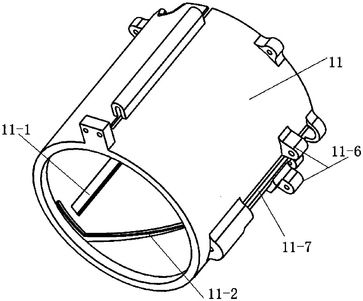
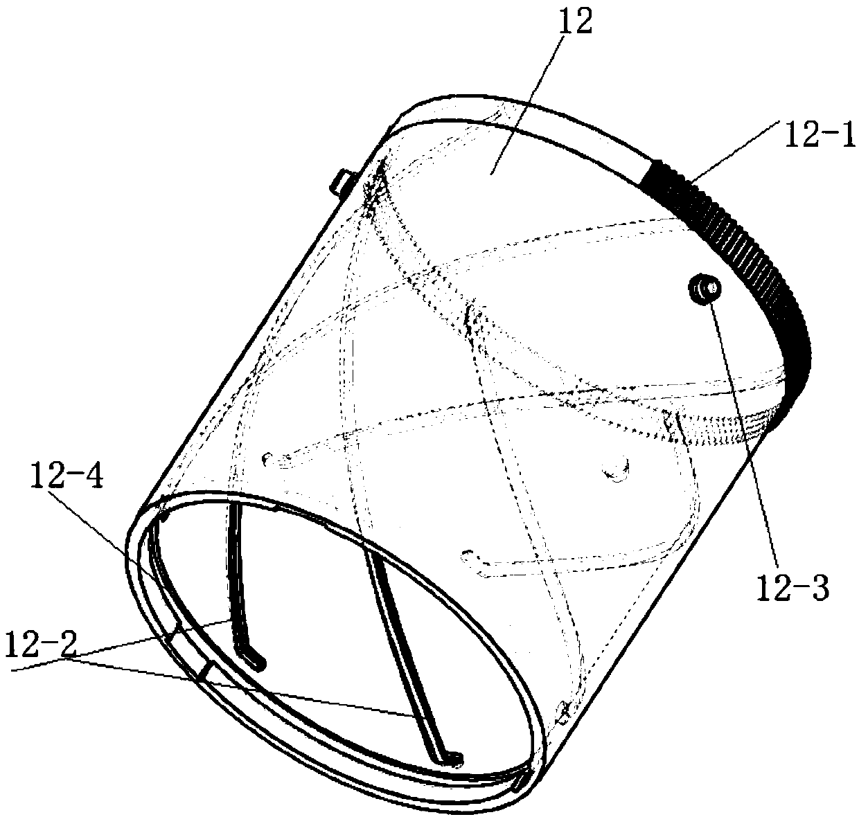
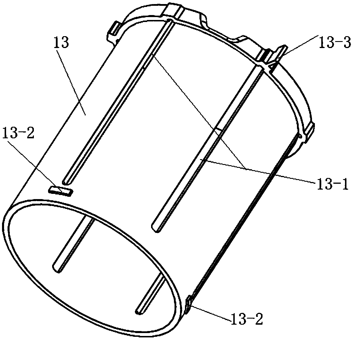
[0045] like Figure 1-5 Shown is a schematic diagram of the structure of the outer sleeve of each layer of this embodiment and a schematic diagram of the overall structure after assembly. The structure of this embodiment will be described in layers below.

[0046] like figure 1 Shown is a schematic structural view of the first layer of the outer sleeve 11 (fixed sleeve) of the present embodiment, combined with Figure 5 , the outer wall of the outer sleeve 11 of the first layer is provided with a motor mount 11-6, the motor 11-5 is installed on the motor mount 11-6, and the output shaft of the motor 11-5 is connected with the pinion 11-4. The outer wall of the first outer cylinder 11 is provided with a through long slot 11-7, and a gear bar 11-3 is installed in the long slot 11-7, and the gear bar 11-3 meshes with the pinion 11-4. The inner wall of the first layer of outer sleeve 11 is axially provided with a first linear groove 11-1 and a first helical groove 11-2. The qua...

Embodiment 2

[0061] like Figure 6-12 Shown is a schematic diagram of the structure of the outer sleeve of each layer of this embodiment and a schematic diagram of the overall structure after assembly. The structure of this embodiment will be described in layers below.

[0062] like Image 6 Shown is the schematic diagram of the structure of the first layer of outer sleeve 21 (fixed sleeve) in this embodiment, and the inner wall of the first layer of outer sleeve 21 is provided with a first linear groove 21-1 and a first spiral groove 21-1 along the axial direction. 2. The number of the first spiral groove 21-2 matches the number of the second protrusion 22-3 on the second layer of outer sleeve 22, and the number of the first linear groove 21-1 matches the number of the third layer of outer sleeve The quantity of the third insert block two 23-3 on the cylinder is matched. It is preferable that the first linear groove 21-1 and the first helical groove 21-2 are not interfered with each oth...


PUM


Abstract

The invention provides a linkage type telescopic arm. The linkage type telescopic arm comprises a driving device, a fixed cylinder and at least one stage of telescopic device, wherein a linear groove and a spiral groove are arranged in the inner wall of the fixed cylinder along the axis, and the telescopic device comprises a rotating cylinder and a translation cylinder; linear grooves and spiral grooves are also designed on the rotating cylinder and the translation cylinder according to design requirements; and the fixed cylinder, the rotating cylinder and the translation cylinder are sequentially nested. By adopting a multi-stage spiral cylinder step-by-step propelling manner and utilizing the fit of the spiral grooves and the linear grooves, the linkage type telescopic arm realizes ordered telescoping, has a large telescoping range in a small space and can realize demanded elongation in a limited space. The linkage type telescopic arm is compact in structure and light in weight and realizes step-by-step linkage telescoping. A telescopic mechanism meeting the requirements of specific product applications has a compact structure and a small size and can be elongated to a required length in the limited space.

Description

technical field [0001] The invention relates to a linked telescopic arm. Background technique [0002] During the daily power station inspection, sometimes the objects inspected by the inspection robot are in a relatively distant location, but cannot be reached due to path restrictions. Therefore, the camera is stretched out through the telescopic mechanism to reduce the distance from the inspected object. However, due to the complex and large structure of the conventionally designed spiral telescopic mechanism, it cannot effectively and quickly perform telescopic movement, and is accompanied by problems such as a high failure rate, resulting in low inspection efficiency. [0003] Chinese invention patent document CN102235840A "A Lifting System for Target Lifting Robot" describes a lifting system using spring control materials. The positioning method is switch positioning, and the pushing rod and relay post interact to complete the lifting function. This device is suitable ...

Claims


Application Information

Patent Timeline
Patent Type & Authority Patents(China)
IPC IPC(8): B25J18/02
CPCB25J18/025
Inventor 毕备吕福彬邱显东赵伟许春山
Owner YIJIAHE TECH CO LTD
Learn More