Manufacturing method of foot drying pad

A manufacturing method and technology for foot pads, which are applied in the field of manufacturing foot pads, can solve the problems of reduced water absorption speed, leaving a damp feeling, slow drying speed, etc., and achieve the effects of low water absorption speed, inhibiting damp feeling, and high water absorption

Inactive Publication Date: 2017-03-22
日本怡饰丽新株式会社
View PDF8 Cites 0 Cited by
  • Summary
  • Abstract
  • Description
  • Claims
  • Application Information

AI Technical Summary

Problems solved by technology

[0008] However, the water absorption speed of the above-mentioned floor mat is not very fast, and if it is used frequently in a short period of time, there is a problem that its water absorption speed will decrease.
Furthermore, there is also a problem that the drying speed is slow and a moist feeling remains for a long time.

Method used


Image

  • Manufacturing method of foot drying pad

Examples


Embodiment 1

[0069] Mix 48 parts by weight of quicklime, 52 parts by weight of silica and 1200 parts by weight of water to prepare raw material slurry. 2 ), stirring the raw material slurry for 4 hours at a temperature of 197° C. and performing a hydrothermal reaction. By this hydrothermal reaction, an aqueous slurry containing secondary particles in which xonotlite and a small amount of tobermorite were mixed was obtained.

[0070] Prepare the above-mentioned water-based slurry of 77 parts by weight in terms of solid content, further, mix 2 parts by weight of bentonite, 16 parts by weight of ordinary Portland cement, 2 parts by weight of waste paper pulp and 3 parts by weight of glass fiber. After the water-based slurry mixed with the above-mentioned various materials is poured into a predetermined amount of mold, it is 2 Dehydration was carried out under pressure, and the obtained dehydrated molded body was dried in the air at 150° C. to obtain an inorganic molded board. A bulk densit...

Embodiment 2

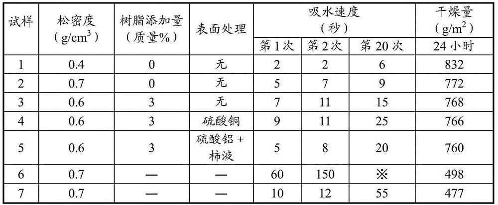
[0072]Prepare the aqueous slurry containing the secondary particles mixed with xonotlite and a small amount of tobermanite obtained in embodiment 1 that is 90 parts by weight in terms of solid content, and further, mix 2 wt. 5 parts by weight of white cement, 5 parts by weight of glass fiber and 3 parts by weight of styrene-acrylate resin. After the water-based slurry mixed with the above-mentioned various materials is poured into a predetermined amount of mold, it is 2 Dehydration was carried out under pressure, and the obtained dehydrated molded body was dried in the atmosphere at 120° C. to obtain an inorganic molded board. A bulk density of 0.6 g / cm was obtained by surface grinding the inorganic formed board. 3 Inorganic forming board. This inorganic form board is sample 3.

Embodiment 3

[0074] The inorganic molded body obtained in the same manner as in Example 2 was cut to a predetermined size. Next, press 100 g / m on one side of the cut inorganic molded body with a brush. 2 After applying a 9% by mass aqueous solution of copper sulfate (industrial copper sulfate was used), drying was performed in the atmosphere at 105° C. for 2 hours. The inorganic shaped body thus obtained (bulk density 0.6 g / cm 3 ) is sample 4.


PUM

PropertyMeasurementUnit
densityaaaaaaaaaa
densityaaaaaaaaaa
densityaaaaaaaaaa

Abstract

The invention provides a manufacturing method of a foot drying pad which is high in water absorbing speed and high in drying speed and cannot become declined in water absorbing speed after continuously used. According to the manufacturing method of the foot drying pad provided by the invention, the foot drying pad is constituted by an inorganic substance molding plate, and the method comprises the following steps: 1, stirring raw material slurry consisting of a calcareous raw material, a siliceous raw material and water, and simultaneously, conducting a hydrothermal reaction, so that waterborne slurry containing calcium silicate secondary particles is obtained; and 2, dehydrating and forming the waterborne slurry obtained in the step 1, so that the inorganic substance molding plate is obtained. The foot drying pad manufactured by the manufacturing method comprises the inorganic substance molding plate which is formed by the calcium silicate crystallized secondary particles and / or a compressive deformation substance of the secondary particles, and the bulk density of the inorganic substance molding plate is 0.2-0.7g / cm3.

Description

technical field [0001] The invention relates to a manufacturing method of a floor mat used in bathrooms, swimming pools and the like. Background technique [0002] At present, the floor mats used in bathrooms and swimming pools are mostly terry cloth and hemp mats, but frequent use in a short period of time will reduce the water absorption capacity, and the situation that the moisture on the wet feet cannot be wiped off occurs. Although the special fiber with high water absorption rate is used for the foot wiper of terry cloth to solve this problem, but because this foot wiper is made of thin cloth, so the water absorption is limited, still needs to be improved. [0003] Based on this point of view, various floor mats that improve the above-mentioned disadvantages have been proposed. For example, Patent Document 1 proposes a floor mat made of a humidity-regulating material (superabsorbent ceramic tile) containing diatomaceous earth and a support stand. In addition, in Pate...

Claims


Application Information

Patent Timeline
Patent Type & Authority Applications(China)
IPC IPC(8): A47K10/00C04B28/00
Inventor 成濑吉昭高桥芳明藤田树里
Owner 日本怡饰丽新株式会社
Why Eureka
Try Eureka