Wideband and wide-angle scanning low-profile array antenna

An array antenna and wide-angle technology, applied in the field of low-profile array antennas, can solve the problems of difficult to balance broadband and wide-angle scanning characteristics, large array antenna volume, complex structure, etc., and achieve easy conformal and integration, good radiation pattern and gain, the effect of increasing the scan angle

Active Publication Date: 2017-03-15
UNIV OF ELECTRONICS SCI & TECH OF CHINA
View PDF1 Cites 6 Cited by
  • Summary
  • Abstract
  • Description
  • Claims
  • Application Information

AI Technical Summary

Problems solved by technology

[0003] What the present invention aims to solve is the problem that the existing array antenna has large volume, complex structure, high section, and difficulty in taking into account the wide-band and wide-angle scanning characteristics

Method used


Image

  • Wideband and wide-angle scanning low-profile array antenna
  • Wideband and wide-angle scanning low-profile array antenna
  • Wideband and wide-angle scanning low-profile array antenna

Examples


Embodiment

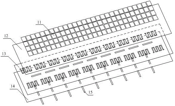
[0028] figure 1 It is a schematic perspective view of the three-dimensional structure of the low-profile array antenna of this embodiment. The low-profile array antenna includes a first dielectric layer 12 , a metal ground layer 13 and a second dielectric layer 14 stacked in order from top to bottom.

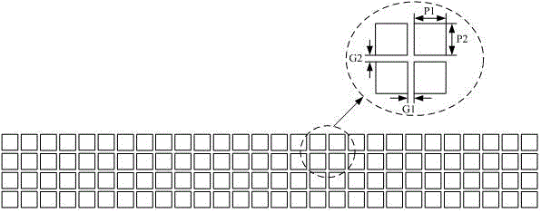
[0029] Specifically, the upper surface of the first dielectric layer 12 is provided with M rows of metal patches 11 arranged in a rectangular array. The rectangular array includes L sub-arrays, each sub-array is composed of M rows and N columns of metal patches, and every two adjacent sub-arrays share K columns of metal patches, wherein L, M and N are positive numbers not less than 2 Integer, K is a positive integer less than N. figure 2 It is a schematic structural diagram of the metal patches 11 arranged in a rectangular array in this embodiment. In this embodiment, M=4, L=9, N=4, and K=1 are taken as examples for illustration. The metal patches 11 arranged in a rectangular...


PUM


Abstract

The present invention discloses a wideband and wide-angle scanning low-profile array antenna. The antenna includes a first dielectric layer, a metal grounding layer and a second dielectric layer which are stacked sequentially from top to bottom; the upper surface of the first dielectric layer is provided with M rows of metal patches distributed as a rectangular array; the rectangular array includes L sub-arrays; each sub-array is composed of metal patches in M rows and N columns; every two adjacent sub-arrays share K columns of metal patches; L feed slits distributed along the row direction of the rectangular array are formed in the metal grounding layer; each feed slit is correspondingly arranged just below one sub-array; the lower surface of the second dielectric layer is provided with L microstrip lines; and one end of each microstrip line is correspondingly adopted as the feed port of one sub-array, and the horizontal projection of the other end of each microstrip line correspondingly perpendicularly intersects with the horizontal projection of one feed slit. Compared with a conventional microstrip patch array, the wideband and wide-angle scanning low-profile array antenna of the present invention has wider bandwidth and a wider scanning angle.

Description

technical field [0001] The invention relates to the technical field of microwave communication, in particular to a low-profile array antenna with wide-band and wide-angle scanning characteristics. Background technique [0002] The rapid development of modern wireless communication technology puts forward the requirements of multi-functionality and high integration of communication system. Array antennas with wide-band and wide-angle scanning characteristics have received extensive attention in smart antenna systems and radar systems. Many scholars at home and abroad have studied how to increase the effective scanning angle of the array: using non-planar arrays (such as cylindrical arrays, multi-faceted arrays) or reconfigurable arrays to achieve wide-angle scanning, non-planar arrays Arrays are usually bulky, and reconfigurable arrays include some complex biasing circuitry. Designing antennas with wide-lobe characteristics is a method to realize wide-angle scanning of plana...

Claims


Application Information

Patent Timeline
Patent Type & Authority Applications(China)
IPC IPC(8): H01Q1/38H01Q1/48H01Q1/50H01Q21/00H01Q21/06
CPCH01Q1/38H01Q1/48H01Q21/0075H01Q21/065
Inventor 赵延文谷立
Owner UNIV OF ELECTRONICS SCI & TECH OF CHINA
Why Eureka
Try Eureka