
Electric furnace transformer body structure for preventing local overheating of transformer winding

An electric furnace transformer and transformer winding technology, applied in the field of transformers, can solve the problems of less turns, affect the characteristics of the transformer, damage the transformer, etc., and achieve the effects of being beneficial to heat exchange and dissipation, preventing uneven current distribution, and eliminating local overheating.

Active Publication Date: 2017-03-15
BAODING TIANWEI GROUP TEBIAN ELECTRIC
View PDF6 Cites 1 Cited by
  • Summary
  • Abstract
  • Description
  • Claims
  • Application Information

AI Technical Summary

Problems solved by technology

[0002] Electric furnace transformer is a transformer designed to provide power for various electric furnaces. For large-capacity electric furnace transformers, the low-voltage windings in the transformer have the characteristics of low voltage, large current, and few turns. During the working process, the low-voltage windings in the transformer are easy to Partial overheating occurs at the end of the winding. Long-term overheating of the winding will not only affect the characteristics of the transformer itself, but also damage the transformer, and even cause danger of explosion.

Method used


Image

  • Electric furnace transformer body structure for preventing local overheating of transformer winding
  • Electric furnace transformer body structure for preventing local overheating of transformer winding

Examples


Embodiment Construction

[0014] The present invention will be described in further detail below with reference to the accompanying drawings and specific embodiments.

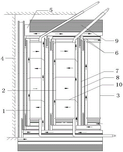
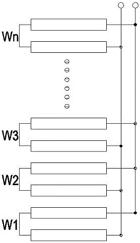
[0015] like figure 1 As shown, it is a structural schematic diagram of an electric furnace transformer body structure for preventing partial overheating of transformer windings according to the present invention, including high-voltage phase-shift winding 1, high-voltage basic winding 2, low-voltage winding 3, iron core 4 and an insulating heat dissipation system; 4 The external installation sequence is high-voltage phase-shift winding 1, high-voltage basic winding 2 and low-voltage winding 3; the insulation cooling system is distributed and installed around the high-voltage phase-shift winding 1, high-voltage basic winding 2 and low-voltage winding 3; low-voltage winding 3 adopts multiple The circuit is connected in parallel with a double-cake structure.

[0016] In this design, the low-voltage winding 3 is placed on the outermost sid...


PUM


Abstract

The invention discloses an electric furnace transformer body structure for preventing local overheating of a transformer winding and relates to the technical field of transformer structure design. The electric furnace transformer body structure comprises a high-voltage phase shift winding, a high-voltage basic winding, a low-voltage winding, an iron core and an insulated cooling system, wherein the high-voltage phase shift winding, the high-voltage basic winding and the low-voltage winding are sequentially arranged from inside of the iron core to outside; the insulated cooling system is distributed and arranged around the high-voltage phase shift winding, the high-voltage basic winding and the low-voltage winding; the low-voltage winding is located at the outmost layer of a transformer body; and the low-voltage winding is in contact with insulating oil close to the outer side of the transformer body. Since the insulating oil at the outer side of the transformer body is relatively low in temperature, heat exchange and emission are facilitated, the heat generated by the low-voltage winding is timely emitted, the overheating phenomenon of the low-voltage winding is prevented, a multichannel parallel double-cake structure is adopted by the low-voltage winding, current generated by the low-voltage winding is uniform in density, and the local overheating phenomenon of the low-voltage winding generated by non-uniform current distribution is prevented.

Description

technical field [0001] The invention relates to the technical field of transformers, in particular to an electric furnace transformer body structure for preventing partial overheating of transformer windings. Background technique [0002] Electric furnace transformer is a kind of transformer that provides power supply for various electric furnaces. For large-capacity electric furnace transformers, the low-voltage windings in the transformer have the characteristics of low voltage, large current and small number of turns. The phenomenon of local overheating at the end of the winding, the overheating of the winding for a long time will not only affect the characteristics of the transformer itself, but also damage the transformer, and even cause danger of explosion. SUMMARY OF THE INVENTION [0003] The technical problem to be solved by the present invention is to aim at the deficiencies of the above-mentioned prior art, and to provide an electric furnace transformer body str...

Claims


Application Information

Patent Timeline
Patent Type & Authority Applications(China)
IPC IPC(8): H01F27/28H01F27/08
CPCH01F27/28H01F27/2876
Inventor 张亚杰张立明孙国刚赵世显常鑫汤鹏
Owner BAODING TIANWEI GROUP TEBIAN ELECTRIC
Learn More