A steady flow spray device

A spray device, a technology of stabilizing flow, applied in the direction of spray device, liquid spray device, spray device with movable outlet, etc., can solve problems such as poor atomization effect of pure water spray, dead angle area of ​​spray, and reduced visibility of production site.

Active Publication Date: 2022-07-08
SHANDONG UNIV OF SCI & TECH
View PDF0 Cites 0 Cited by
  • Summary
  • Abstract
  • Description
  • Claims
  • Application Information

AI Technical Summary

Problems solved by technology

Mine dust has hazards such as reducing the service life and precision of equipment, reducing the visibility of the production site, and causing occupational diseases (pneumoconiosis) for long-term dust-exposed personnel. Coal dust also has the danger of explosion
Spray dust reduction is the most common way in the mine production process, but often due to the instability of the spray water pressure, the water spray volume of the nozzle is suddenly large and small, resulting in poor spray effect, and the fixed nozzle atomization angle of the mine is limited. There are problems such as dead angle areas and poor atomization effect of pure water spray

Method used


Image

  • A steady flow spray device
  • A steady flow spray device
  • A steady flow spray device

Examples


Embodiment Construction

[0013] The present invention provides a steady flow spraying device. In order to make the purpose, technical solution and effect of the present invention clearer and clearer, the present invention will be described in further detail below. It should be understood that the specific embodiments described herein are only used to explain the present invention, but not to limit the present invention.

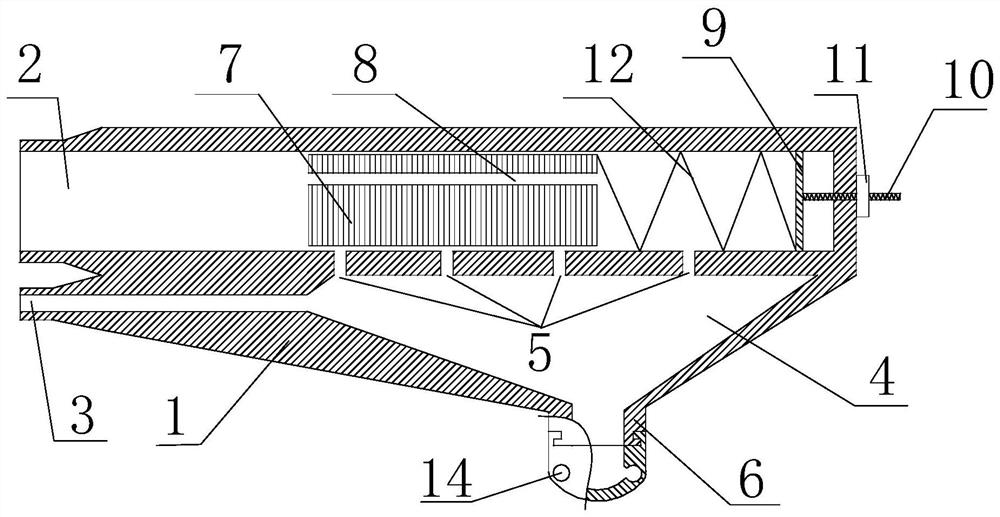
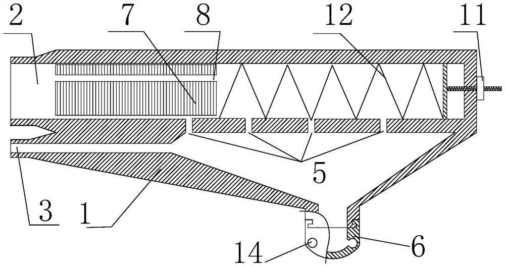
[0014] The present invention provides a steady flow spray device, such as figure 1 and figure 2 As shown, it includes a base 1, wherein the base 1 is provided with a water inlet pipe 2 and an air inlet pipe 3, the front end of the base 1 is provided with an atomization chamber 4, the air inlet pipe 3 is communicated with the atomization chamber 4, and the water inlet pipe 2 Located above the atomization chamber 4, the water inlet pipe 2 is evenly arranged with a plurality of water inlet holes 5 corresponding to the atomization chamber 4, the water inlet holes 5 are all communicated...


PUM


Abstract

The invention discloses a steady flow spraying device. A water inlet pipe and an air inlet pipe are arranged on a base, an atomization chamber is arranged at the front end of the base, the air inlet pipe is communicated with the atomization chamber, and the water inlet pipes are evenly arranged at the positions corresponding to the atomization chamber. There are a plurality of water inlet holes, the water inlet holes form a water inlet area, and an adjustment structure is arranged in the water inlet area, and the adjustment structure is used to keep the flow rate entering the atomization chamber from the water inlet pipe unchanged. When the water flow enters the atomizing chamber through the water inlet hole of the water inlet pipe, the water droplets are blown and broken into smaller mist droplets under the high pressure gas, which improves the atomization effect. At the same time, when the water pressure in the water inlet pipe is small, the adjustment structure makes Multiple water inlet holes are connected with the atomization chamber, which increases the water flow area and ensures that the flow rate remains unchanged under the condition of low water speed. When the water pressure in the water inlet pipe is large, the adjustment structure blocks the corresponding water inlet holes, only The corresponding water inlet hole is communicated with the atomization chamber, reducing the area of ​​the water outlet, ensuring that the flow rate remains unchanged under the condition of high water speed, thereby ensuring the stability of the nozzle spray.

Description

technical field [0001] The invention relates to the field of spray dust reduction, in particular to a steady flow spray device. Background technique [0002] In the process of mine production, a large amount of dust is generated, especially the high-yield and efficient mining process with a high degree of mechanization, so that the dust in the underground air always maintains a high concentration. Mine dust has the hazards of reducing the service life and accuracy of equipment, reducing the visibility of production sites, and causing occupational diseases (pneumoconiosis) of long-term dust-exposed personnel. Coal dust also has the danger of explosion. Spray dust reduction is the most common method in the mine production process, but often due to the instability of the spray water pressure, the water spray volume of the nozzle is suddenly large or small, resulting in poor spray effect, and the fixed nozzle of the mine has a limited atomization angle, and the spray There are ...

Claims


Application Information

Patent Timeline
Patent Type & Authority Patents(China)
IPC IPC(8): B05B3/06B05B7/32B05B13/02B05B12/08
CPCB05B3/06B05B7/32B05B12/085B05B13/0278Y02A20/411
Inventor 薛娇刘国明于欣崔向飞刘林胜
Owner SHANDONG UNIV OF SCI & TECH
Why Eureka
Try Eureka