Radio frequency module
A technology of high-frequency modules and module substrates, applied in the direction of electrical components, multi-terminal pair networks, transmission systems, etc., to achieve the effect of improving isolation characteristics and improving attenuation characteristics
- Summary
- Abstract
- Description
- Claims
- Application Information
AI Technical Summary
Problems solved by technology
Method used
Image

Examples
no. 1 approach >
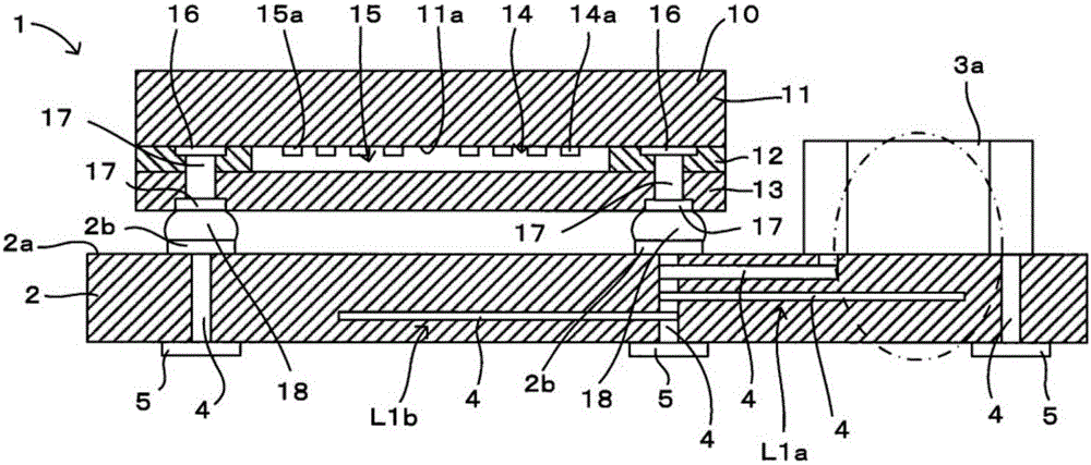
[0035] refer to Figure 1 ~ Figure 4 A first embodiment of the high-frequency module according to the present invention will be described. In addition, in figure 1 as well as figure 2In the figure, only the main configurations related to the present invention are shown, and other configurations are omitted from illustration for simplicity of description. In addition, each drawing referred to in the following description is also the same as figure 1 as well as figure 2 In the same way, only the main configurations are shown, and the description thereof will be omitted in the following description.
[0036] (high frequency module)
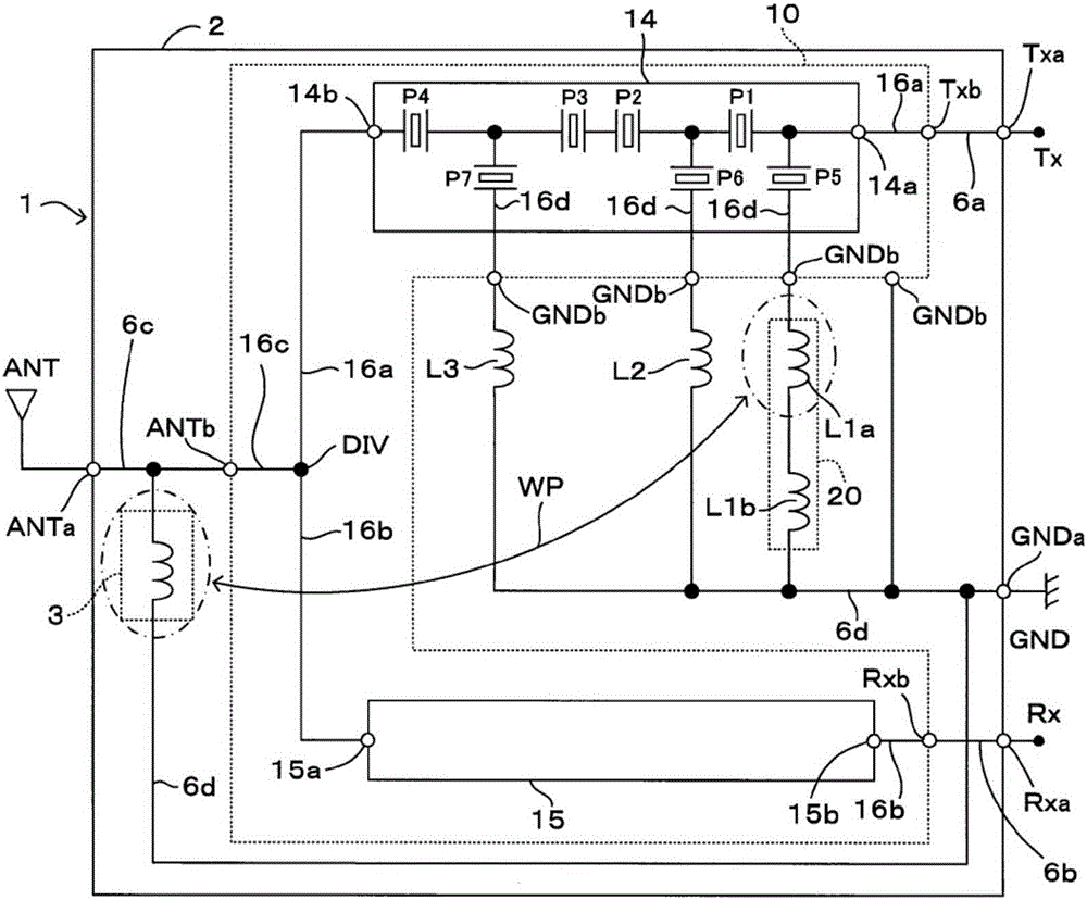
[0037] figure 1 as well as figure 2 The shown high-frequency module 1 is mounted on a mother board provided in a communication mobile terminal such as a mobile phone or a mobile information terminal. device), module substrate 2, matching circuit 3, inductor circuit 20, switch IC, filter, resistor, capacitor, coil and other electronic co...
no. 2 approach >
[0085] refer to Figure 5 as well as Image 6 A second embodiment of the high-frequency module according to the present invention will be described.
[0086] like Figure 5 as well as Image 6 As shown, the difference between this embodiment and the above-mentioned first embodiment is that the wiring electrode 4 forming the first inductor L1a is arranged directly under the wave splitter 10, and the first inductor L1a is connected to the transmission path 16a in the wave splitter Alternatively, the reception paths 16b in the duplexer are connected at high frequency by electromagnetic field coupling to form the propagation path WP. In addition, between the first inductor L1a and the second inductor L1b, the ground electrode 30 for shielding formed by the wiring electrode 4 connected to the ground terminal GNDa of the module substrate suppresses the first inductor L1a and the second inductor L1a. The electromagnetic field coupling method of L1b is configured between the first...
no. 3 approach >
[0089] refer to Figure 7 A third embodiment of the high-frequency module according to the present invention will be described. Figure 7 It is a diagram when a part (main part) of the module substrate 2 of the high-frequency module 1 is planarly viewed from the mounting surface 2a side.
[0090] like Figure 7 As shown, this embodiment is different from the above-mentioned first embodiment in that the chip-type surface mount component 7 forming the first inductor L1a and the chip-type surface mount component 3a (inductor) forming the matching circuit 3 are mounted on The mounting surface 2 a of the module substrate 2 and the surface mounting component 7 are disposed adjacent to the surface mounting component 3 a. In addition, as shown in the figure, the surface mount component 7 and the area where the wiring electrodes 4 forming the second inductor L1b are arranged are arranged so as not to overlap each other in plan view. The other configurations are the same as those of ...
PUM
 Abstract
Description
Claims
Application Information
 - R&D
- Intellectual Property
- Life Sciences
- Materials
- Tech Scout
- Unparalleled Data Quality
- Higher Quality Content
- 60% Fewer Hallucinations
Browse by: Latest US Patents, China's latest patents, Technical Efficacy Thesaurus, Application Domain, Technology Topic, Popular Technical Reports.
© 2025 PatSnap. All rights reserved.Legal|Privacy policy|Modern Slavery Act Transparency Statement|Sitemap|About US| Contact US: help@patsnap.com