Elastic wave filter device

An elastic wave filter and filter electrode technology, applied in impedance networks, electrical components, etc., can solve problems such as deterioration of attenuation characteristics, and achieve the effect of excellent attenuation characteristics

Active Publication Date: 2014-02-26
MURATA MFG CO LTD
View PDF6 Cites 3 Cited by
  • Summary
  • Abstract
  • Description
  • Claims
  • Application Information

AI Technical Summary

Problems solved by technology

As a result, the attenuation characteristics outside the passband of the elastic wave filter device may deteriorate due to the leaked signal.

Method used


Image

  • Elastic wave filter device
  • Elastic wave filter device
  • Elastic wave filter device

Examples


no. 1 approach

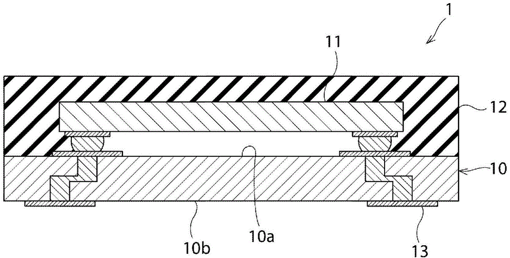
[0026] figure 1 It is a schematic cross-sectional view of the elastic wave filter device according to this embodiment. figure 1 The shown elastic wave filter device 1 includes: a receiving filter unit corresponding to the communication system of GSM (registered trademark) 850 (used frequency band: 869-894 MHz); ) communication method, reception filter unit compatible with GSM (registered trademark) 1800 (used frequency band: 1805-1880MHz), and GSM (registered trademark) 1900 (used frequency band: 1930-1990MHz) A total of four reception filter sections 21 to 24 are reception filter sections corresponding to the communication method. In addition, the acoustic wave filter device 1 may be a surface acoustic wave filter device using a surface acoustic wave or a boundary acoustic wave filter device using a boundary acoustic wave.

[0027] Such as figure 1 As shown, the elastic wave filter device 1 includes a wiring board 10 and an elastic wave filter chip 11 . The elastic wave f...


PUM


Abstract

Provided is an elastic wave filter device that exhibits an excellent attenuation characteristics except within the passband. The elastic wave filter device (1) is equipped with filter electrode sections (21a-24a) that are provided on a piezoelectric substrate (20) and constitute elastic wave filter sections (21-24). Input signal lines (41, 43) have adjoining sections (41a, 43a) that adjoin output signal lines (51a, 52b). The distance between each adjoining section (41a, 43a) and a corresponding ground line (61, 62) that is connected to the ground potential is shorter than the distance between the adjoining section (41a, 43a) and the corresponding output signal line (51a, 52b).

Description

technical field [0001] The present invention relates to an elastic wave filter device, and more particularly to a multi-band elastic wave filter device in which a plurality of filter sections are formed using a single piezoelectric substrate. Background technique [0002] In recent years, in the progress of downsizing and multibanding of mobile phones, there has been a demand for downsizing and multibanding of elastic wave filter devices used in RF circuits of mobile phones. As a measure to reduce the size and multiband of the elastic wave filter device, it is conceivable to configure a plurality of elastic wave filter sections using a single piezoelectric substrate. However, in this case, the routing of the wiring becomes complicated, and a part of the wiring approaches to generate parasitic capacitance. For example, when the input signal wiring through which the input signal flows is close to the output signal wiring through which the output signal flows, unnecessary powe...

Claims


Application Information

Patent Timeline
IPC IPC(8): H03H9/64H03H9/145
CPCH03H9/64H03H9/145H03H9/0057H03H9/1092
Inventor 乘地隆礼
Owner MURATA MFG CO LTD
Why Eureka
Try Eureka