
Power cabinet

A power cabinet and body technology, applied in electrical components, substation/distribution device housing, substation/switch layout details, etc., can solve problems such as airtightness, power cabinets susceptible to moisture, water ingress, rust, equipment damage, etc.

Inactive Publication Date: 2017-02-22
蓝灿玉
View PDF1 Cites 1 Cited by
  • Summary
  • Abstract
  • Description
  • Claims
  • Application Information

AI Technical Summary

Problems solved by technology

[0002] Many power cabinets are used outdoors. Due to the influence of weather factors, in rainy and snowy weather, the power cabinets are easily affected by moisture, water, and corrosion, which affects the safe use of electricity. There are many live devices in the power cabinets, so Water as a conductor must be isolated. However, due to the large temperature difference between day and night in the operating environment of the power cabinet, it is easy to cause dew condensation in the cabinet, especially when the condensed dew is located on the inner wall of the upper panel of the cabinet. The installed equipment is easy to cause a short circuit due to falling dew, resulting in equipment damage. In the prior art, it is generally a welded structure and a plate structure. A power cabinet is mentioned in Chinese utility model CN ​​204258084 U. Due to the philosophy The structure is airtight, which leads to high temperature inside the cabinet, which is not conducive to the operation of other devices inside the cabinet, and the cooling device is installed, which also needs to be opened for a long time, and the effect of energy saving cannot be achieved. Usually, the power cabinet installed outdoors , boxes, small animals are easy to drill into, build nests and build nests, threaten the safe operation of the power grid, cause power grid losses, power outages for users, and reduce power supply and power supply reliability. Therefore, the above problems are the object of the present invention. Therefore, we propose a power cabinet

Method used


Image

  • Power cabinet
  • Power cabinet

Examples


Embodiment Construction

[0013] The following will clearly and completely describe the technical solutions in the embodiments of the present invention with reference to the accompanying drawings in the embodiments of the present invention. Obviously, the described embodiments are only some, not all, embodiments of the present invention. Based on the embodiments of the present invention, all other embodiments obtained by persons of ordinary skill in the art without making creative efforts belong to the protection scope of the present invention.

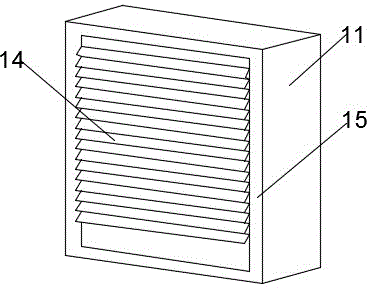
[0014] see Figure 1-2 , the present invention provides a technical solution: a power cabinet, including a power cabinet body 11, the body 11 is provided with a top plate 7, the top plate 7 is provided with a rain shelter 1, and the body 11 is provided with a left plate 2 and a right plate 10 , the body 11 is provided with a back plate 15, the back plate 15 is provided with a plate 14, the left plate 2 and the right plate 10 are provided with pearl cotton 9, t...


PUM


Abstract

The invention discloses a power cabinet which comprises a power cabinet body. A top plate is arranged on the body, a rain shed is arranged on the top plate, a left plate and a right plate are arranged on the body, a back plate is arranged on the body, a plate block is arranged on the back plate, the left plate and the right plate are provided with pearl wool, and a base plate is arranged on the body. The power cabinet has a rainproof effect, can prevent small insects from climbing into the power cabinet and damaging the cabinet, can prevent a water body attaching to the inner wall of the cabinet body from falling into the device, and the problem that poor heat dissipation and energy saving of the power cabinet is solved. Most of cabinets in the prior art are generally of welding structures and plate block structures, the internal temperature of the cabinets is slightly high due to airtight philosophical structures and is not conductive to operation of other devices inside cabinet bodies.

Description

technical field [0001] The invention relates to the technical field of metal processing, in particular to an electric power cabinet. Background technique [0002] Many power cabinets are used outdoors. Due to the influence of weather factors, in rainy and snowy weather, the power cabinets are easily affected by moisture, water, and corrosion, which affects the safe use of electricity. There are many live devices in the power cabinets, so Water as a conductor must be isolated. However, due to the large temperature difference between day and night in the operating environment of the power cabinet, it is easy to cause dew condensation in the cabinet, especially when the condensed dew is located on the inner wall of the upper panel of the cabinet. The installed equipment is easy to cause a short circuit due to falling dew, resulting in equipment damage. In the prior art, it is generally a welded structure and a plate structure. A power cabinet is mentioned in Chinese utility mod...

Claims


Application Information

Patent Timeline
Patent Type & Authority Applications(China)
IPC IPC(8): H02B1/30H02B1/28H02B1/56
CPCH02B1/30H02B1/28H02B1/565
Inventor 蓝灿玉
Owner 蓝灿玉
Learn More