
A high voltage relay

A technology of high-voltage relays and relays, applied in the direction of relays, electromagnetic relays, detailed information of electromagnetic relays, etc., can solve the problems of high power consumption, heating of relay coils, and inability to use multiple relays at the same time, so as to reduce power consumption and switch reliably Effect

Active Publication Date: 2019-07-12
XI AN JIAOTONG UNIV +1
View PDF7 Cites 0 Cited by
  • Summary
  • Abstract
  • Description
  • Claims
  • Application Information

AI Technical Summary

Problems solved by technology

Existing high-voltage relays generally adopt a single-spring guiding carriage structure, using a compression spring. The disadvantage of this relay is that the guiding carriage and contact knife are easy to shift left and right, and there is no part to adjust the position of the contact knife, resulting in When the relay is closed, the contact knife and the contact cannot be in good contact
Existing high-voltage relays do not take this characteristic of the relay into consideration, and apply the same current to the coil when the relay state is switched and maintained in the normally open state, so that the power consumption of the relay is too large, and the magnetic core is easily saturated, and the relay coil is seriously heated or even burned. At the same time, due to the excessive power consumption of this kind of high-voltage relay, it is limited by the power supply, so it is impossible to use multiple relays in one device at the same time

Method used


Image

  • A high voltage relay
  • A high voltage relay
  • A high voltage relay

Examples


Embodiment Construction

[0016] In order to better understand the present invention, the present invention will be further described in conjunction with the accompanying drawings and specific embodiments herein.

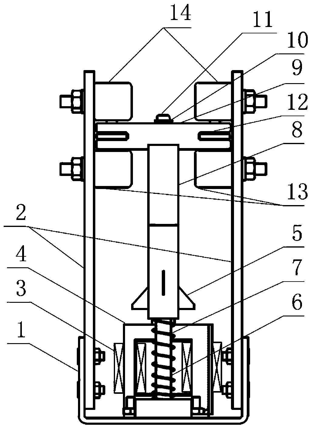
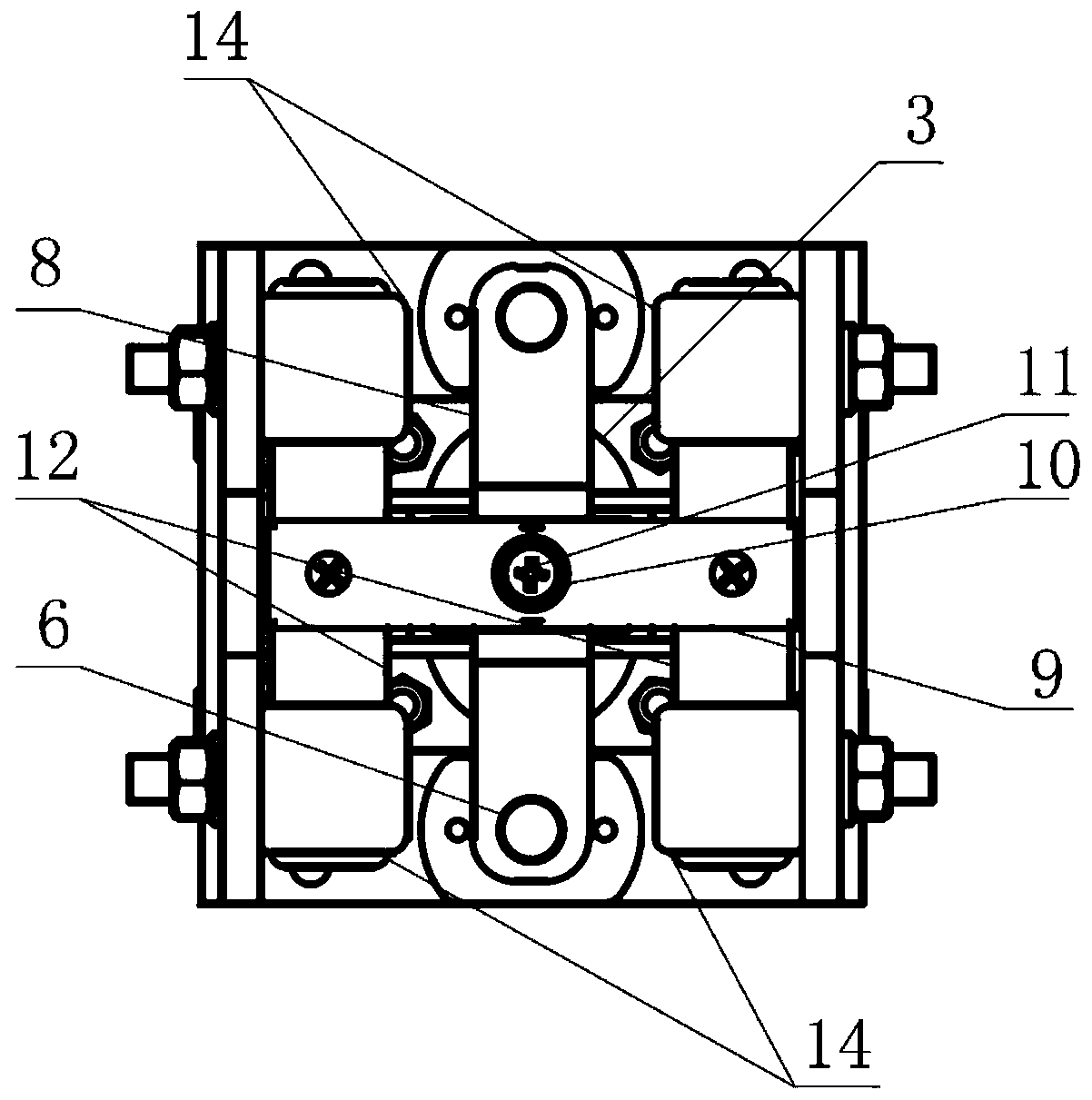
[0017] In one embodiment, the present invention discloses a high-voltage relay, which includes: a bottom plate, a first contact bracket, a second contact bracket, a first compression spring bracket, a second compression spring bracket, a first compression spring , the second compression spring, guide sliding frame, contact knife holder, contact knife, normally open contact, normally closed contact, yoke, armature, control board;

[0018] The bottom plate is used to support the contact bracket and the yoke;

[0019] The first and second contact brackets are used to support normally open contacts and normally closed contacts;

[0020] The first and second compression spring brackets are used to enable the first and second compression springs and the guide sliding frame to achieve compression ...


PUM


Abstract

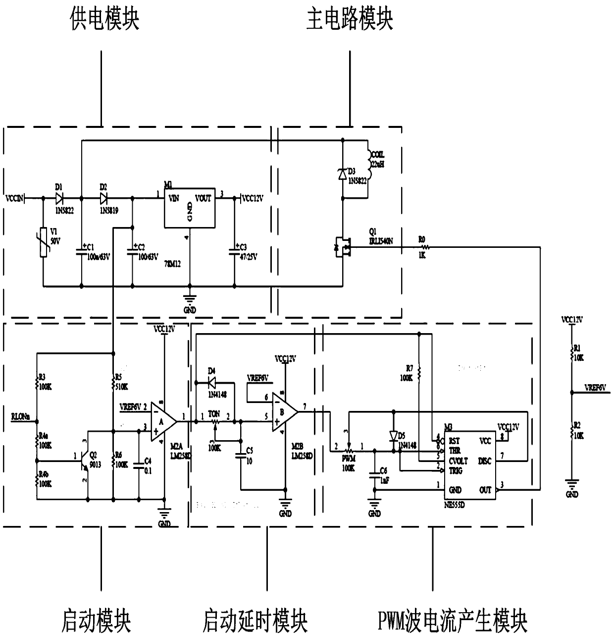
The invention discloses a high-voltage relay. The high-voltage relay comprises a bottom plate, a contact bracket, a coil, a yoke iron, an armature, two compression spring brackets, two compression springs, a guiding sliding frame, a contact knife rest, a positioning buffering spring, a limiting threaded rod, a contact knife, two groups of normally-open contacts, two groups of normally-closed contacts, and a control plate, wherein the relay can avoid left and right offset of the guiding sliding frame and the contact knife rest by virtue of the design of the two compression spring brackets; by virtue of the design of the positioning buffering spring, the position of the contact knife of the relay can be adjusted so as to ensure the tight contact between the contact knife and the contacts; a relay control circuit has a time-delay function; a continuous current flows through the coil in a state switching stage, so that reliable state switching of the relay is ensured; and after the time-delay is performed, a PWM wave current is switched to maintain the relay in a normally-open state, so that the consumption power of the relay is effectively lowered.

Description

technical field [0001] The invention belongs to the field of relays, in particular to a high-voltage relay. Background technique [0002] The high-voltage relay is a widely used electronic control device. Its basic principle is to control the state of the relay by controlling the current of the coil, thereby controlling the cutting and connecting of the high-voltage circuit. Whether its working status is good or not directly affects the operating status of high-voltage equipment. Existing high-voltage relays generally adopt a single-spring guide carriage structure, using a compression spring. The disadvantage of this relay is that the guide carriage and the contact knife are easy to shift left and right, and there is no part to adjust the position of the contact knife, resulting in When the relay is closed, the contact knife cannot make good contact with the contact. On the other hand, in practical applications, the switching current value of the relay (that is, the minimu...

Claims


Application Information

Patent Timeline
Patent Type & Authority Patents(China)
IPC IPC(8): H01H50/54
CPCH01H50/54
Inventor 刘轩东孔德志应之璇李少斌孙玮
Owner XI AN JIAOTONG UNIV
Learn More