
Sunglass lens

A technology of sunglasses and lenses, applied in the field of sunglasses lenses, can solve the problems of impolite wearer, discomfort of communicators, light pollution, etc., and achieve the effect of improving light pollution, reducing reflection effect, and avoiding impoliteness

Pending Publication Date: 2017-02-22
浙江宝乐维科技有限公司
View PDF6 Cites 2 Cited by
  • Summary
  • Abstract
  • Description
  • Claims
  • Application Information

AI Technical Summary

Problems solved by technology

[0003] The outer surface of existing sunglasses is bright after coating and has a certain metallic luster. Although it can make the wearer more eye-catching and beautiful, the coating will produce a strong reflective effect, which not only makes people around the wearer feel Dazzling, forming light pollution, even when communicating face-to-face with the wearer, you can see yourself under the reflection of the lens, making the communicator feel that you are talking to yourself, which causes discomfort to the communicator, and then feels that the glasses are "impolite", and even is the wearer impolite
Although the patent application number CN200610033336.3 discloses adding a polarizing layer on the lens, which has a certain effect of weakening the reflection, but there is still a certain amount of reflection, and the mirror can still form a shadow, and you can see yourself under the reflection from the lens , so it needs to be improved

Method used


Image

  • Sunglass lens
  • Sunglass lens
  • Sunglass lens

Examples


Embodiment 1

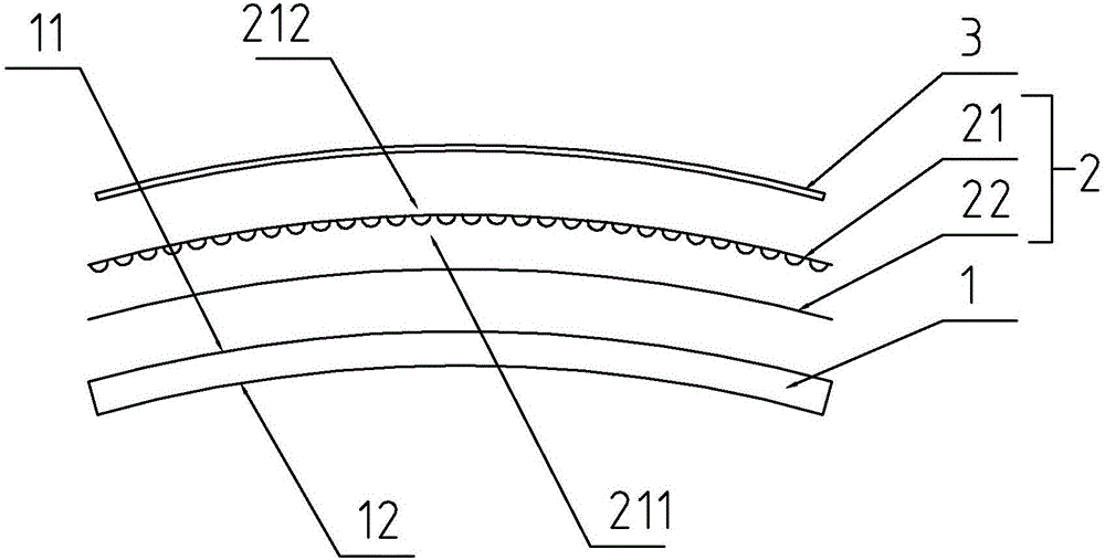
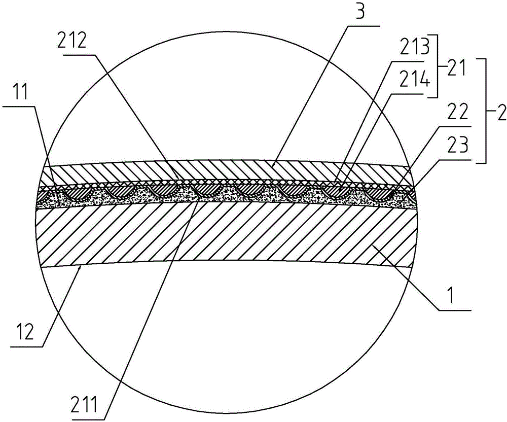
[0026] Embodiment one: refer to figure 1As shown, when the matte layer 2 is attached to the arc-shaped convex surface 11, the smooth surface 212 is bonded with the hard TAC film 3 to form, the color electroplating layer 22 is plated on the hazy matte surface 211, and the matte sheet 21 faces the color electroplating layer One side of 22 is then bonded with the curved convex surface 11 through the glue filling layer 23; when the light is irradiated from the convex side of the lens to the concave side, the light will be directly folded back or diffused through the matte layer 2, and the line of sight is from the lens. The line of sight is transmitted when projecting from the concave side to the convex side. Its principle is: the color electroplating layer 22 is to plate a layer of metal layer with color on the foggy surface 211, and this metal layer belongs to high refraction material; The metal layer particles on the electroplating are about 0.1-0.2um in diameter, and the meta...

Embodiment 2

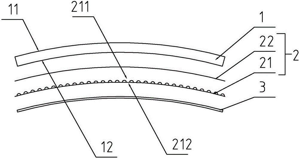
[0027] Embodiment two: refer to figure 2 As shown, when the matte layer 2 is attached to the arc-shaped concave surface 12, the smooth surface 212 and the hard TAC film 3 are bonded to form, the color electroplating layer 22 is plated on the hazy matte surface 211, and the matte sheet 21 faces the color electroplating layer One side of 22 is bonded with the curved concave surface 12 through the glue filling layer 23 to form; when light is irradiated from the convex side of the lens to the concave side, the light will be directly folded back or diffused through the matte layer 2, and the line of sight from the lens The line of sight is transmitted when projecting from the concave side to the convex side. Although the principle is similar to when the matte layer 2 is attached to the curved convex surface 11, it is also because the light is directly irradiated onto the electroplating layer after the curved light filtering of the base layer 1 of the mother sheet, and the light is...


PUM


Abstract

The invention discloses a sunglass lens. The technical scheme mainly includes that the sunglass lens comprises a master slice base layer; the master slice base layer comprises an arc-shaped convex surface and an arc-shaped concave surface, a matte layer capable of directly refracting back or diffusing off light rays from the outside to the inside without obstructing sight from the inside to the outside clings onto the arc-shaped convex surface or the arc-shaped concave surface, and the matte layer and the master slice base layer are adhered and formed with each other; the matte layer comprises a matte slice, a color electroplated layer and a glue filled layer, the matte slice comprises a dim fogging surface and a smooth surface, the color electroplated layer is plated on the dim fogging surface, and the glue filled layer is adhered and arranged between the color electroplated layer and the master slice base layer. The sunglass lens has the advantages that reflected light can be eliminated after the matte layer is adhered on the sunglass lens, the problem that people around a wearer feel dazzling due to strong reflected light of existing lenses under the sunlight can be solved, and accordingly the sunglass lens is favorable for abating light pollution; the sunglass lens is free of mirror effects, and accordingly the problem of impoliteness due to the fact that communicators can see selves under reflected light from the existing lenses when communicating with the wearer face to face can be effectively solved.

Description

technical field [0001] The invention relates to the technical field of lens processing and manufacturing, more specifically, it relates to a sunglass lens. Background technique [0002] Sunglasses, also known as sunshade mirrors, are used for sunshade. People usually rely on adjusting the pupil size to adjust the luminous flux in the sun. When the light intensity exceeds the adjustment ability of the human eye, it will cause damage to the human eye. Therefore, in outdoor activities, especially in summer, it is necessary to use sunshade mirrors to block the sun, so as to reduce the fatigue caused by eye adjustment or the damage caused by strong light stimulation. [0003] The outer surface of existing sunglasses is bright after coating and has a certain metallic luster. Although it can make the wearer more eye-catching and beautiful, the coating will produce a strong reflective effect, which not only makes people around the wearer feel Dazzling, forming light pollution, eve...

Claims


Application Information

Patent Timeline
Patent Type & Authority Applications(China)
IPC IPC(8): G02C7/10
CPCG02C7/10
Inventor 曹汉伟
Owner 浙江宝乐维科技有限公司
Learn More