
A Method for Preventing Chip Fuses from Mis-blowing

A fuse and fusing technology, applied in printed circuit testing, instruments, measuring devices, etc., can solve problems such as continuous fusing, expensive laser trimming, chip damage, etc., and achieve the effect of increasing resistance

Active Publication Date: 2020-11-13
SINO IC TECH
View PDF8 Cites 0 Cited by
  • Summary
  • Abstract
  • Description
  • Claims
  • Application Information

AI Technical Summary

Problems solved by technology

[0006] However, in the process of fusing the trimming pad, false blowing may occur. For example, the fuse between the first trimming pad and the second trimming pad needs to be blown. As a result, the fuse between the first trimming pad and the second trimming pad is blown. At the same time, the fuse between the third trimming pad and the fourth trimming pad is also blown, so that there is a false blown phenomenon.
[0007] In the prior art, in order to avoid false fusing, the following two methods are usually used for improvement: 1. Upgrade the hardware; instead of using voltage and current trimming, laser trimming is used. However, laser trimming is often expensive. The cost is relatively high; 2. Repair by means of current limiting and voltage limiting, that is, through non-stop experiments to obtain more effective voltage values ​​and more effective current values, and set voltage and current values ​​to prevent false fuses
However, this solution also has great disadvantages: 1. It is necessary to pass continuous experiments to confirm the voltage value and current value, which will cause unnecessary chip damage and reduce the yield rate; 2. The voltage value and current are not easy to determine. If the setting is too large, false fusing may occur; if the setting is too small, continuous fusing may occur; 3. The electrical characteristics and process of the chip itself may cause relatively large deviations between different chips

Method used


Image

  • A Method for Preventing Chip Fuses from Mis-blowing

Examples


Embodiment Construction

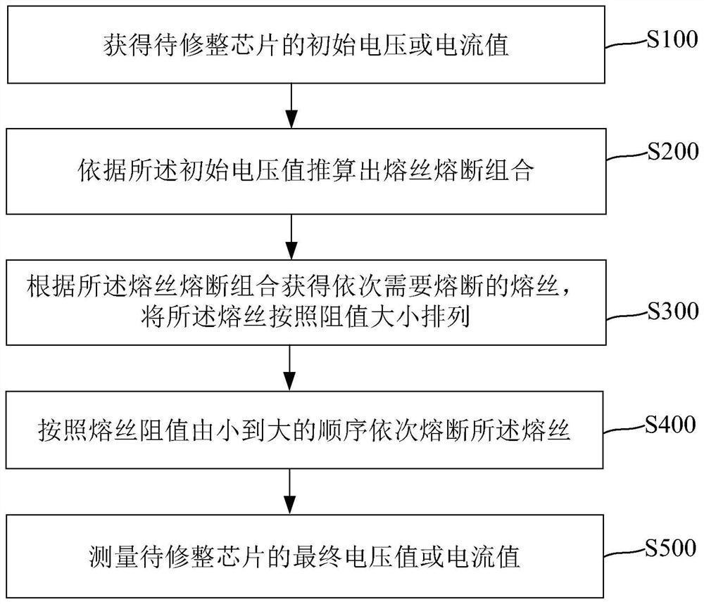
[0023] The method for preventing the false blowing of the chip fuse of the present invention will be described in more detail below in conjunction with the schematic diagram, wherein a preferred embodiment of the present invention is shown, it should be understood that those skilled in the art can modify the present invention described here, and still realize the present invention Beneficial effects of the invention. Therefore, the following description should be understood as the broad knowledge of those skilled in the art, but not as a limitation of the present invention.

[0024] In the interest of clarity, not all features of an actual implementation are described. In the following description, well-known functions and constructions are not described in detail since they would obscure the invention with unnecessary detail. It should be appreciated that in the development of any actual embodiment, numerous implementation details must be worked out to achieve the developer'...


PUM


Abstract

The invention provides a method for preventing mis-fusing of chip fuses. The fuses are fused sequentially according to fuse resistance from low to high, thereby preventing the low-resistance fuse from being fused when the high-resistance fuse is fused; and when the low-resistance fuse is fused first and then the high-resistance fuse is fused, the fused low-resistance fuse can improve the resistance and avoid mis-fusing caused by leak current.

Description

technical field [0001] The invention relates to the field of semiconductor manufacturing, in particular to a method for preventing chip fuses from blown by mistake. Background technique [0002] In chip testing, trimming (Trimming) testing is a very important testing part, which can improve the accuracy of certain parameters. [0003] Trimming refers to the technology of adjusting certain parameters of the chip by writing data into the chip from the outside after the chip is manufactured. Usually, many fuses (e-fuse) are designed on the chip. If a certain fuse is blown, it is equivalent to connecting a resistor in series or in parallel for the circuit. If the resistance value of a certain fuse is controlled in advance, then according to A certain combination of fuses can accurately control the size of the final resistance added to the circuit to meet the needs of certain parameters that require high precision. [0004] Trim test process: ATE (Integrated Circuit Automatic T...

Claims


Application Information

Patent Timeline
Patent Type & Authority Patents(China)
IPC IPC(8): G01R31/26G01R31/28
CPCG01R31/26G01R31/281G01R31/2818
Inventor 顾春华牛勇刘远华王华张杰郝丹丹
Owner SINO IC TECH
Learn More