Eureka AIR delivers breakthrough ideas for toughest innovation challenges, trusted by R&D personnel around the world.

Power supply line detection method

A line detection and power supply technology, applied in the direction of measuring devices, instruments, fault locations, etc., can solve problems such as difficult to judge faulty lines and line branches, power grid loss, complex branch lines of power supply network line structure, etc., to achieve rapid faults Restoration and Power Effects

Inactive Publication Date: 2017-02-22
国网山东省电力公司平度市供电公司
View PDF0 Cites 3 Cited by
  • Summary
  • Abstract
  • Description
  • Claims
  • Application Information

AI Technical Summary

Problems solved by technology

At present, the line fault finder is usually installed on the distribution line. Once the line fails, the line patrol personnel can use the alarm display unit of the addresser to determine the fault point and eliminate the fault. However, the disadvantage is that the fault section cannot be quickly and accurately judged. The inspection takes a long time and is difficult, and the accident cannot be dealt with in a timely and effective manner, which may easily cause the loss of the power grid
[0003] The structure of the power supply network line is complex and there are many branch lines. In addition, the neutral point of the power supply network line is mostly ungrounded or grounded through the arc suppression coil. This makes it difficult to judge the failure of the power supply network line. Lines and line branches require the power supply department to deploy a large number of line inspection and troubleshooting personnel, which increases the maintenance and inspection costs of the power supply company

Method used


Image

  • Power supply line detection method
  • Power supply line detection method

Examples


Embodiment Construction

[0016] The following clearly and completely describes the technical solutions in the embodiments of the present invention. Obviously, the described embodiments are only some of the embodiments of the present invention, but not all of them. All other embodiments obtained by persons of ordinary skill in the art based on the embodiments of the present invention belong to the protection scope of the present invention.

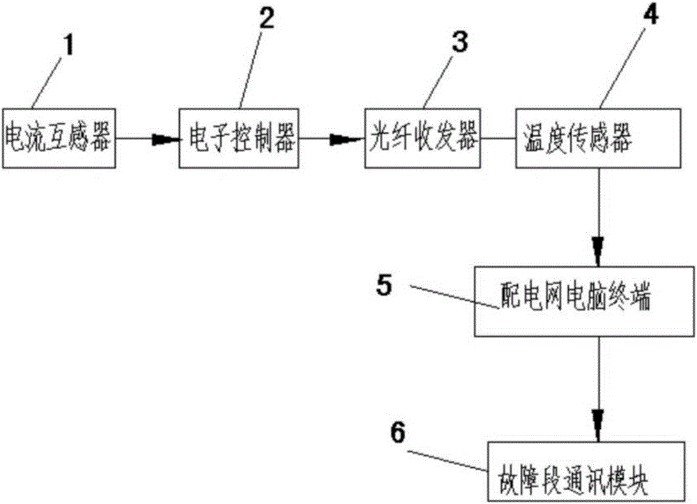
[0017] According to an embodiment of the present invention, a distribution line fault detection device is provided, which mainly includes the following components: a current transformer 1, an electronic controller 2, an optical fiber transceiver 3, a temperature sensor 4, a distribution network computer terminal 5, Fault segment communication equipment6.

[0018] According to an embodiment of the present invention, a power supply line detection method is provided, including the following description, the current transformer 1 is set on the distribution line to coll...


PUM


Abstract

The invention discloses a power supply line detection method including an electronic controller, a fiber transceiver, a temperature sensor, a distribution network computer terminal, and a faulty section communication device. The result of whether the relay protection is required is determined by the result of the real-time frequency analysis of the voltage parameters and the AC signal, so that the accuracy of relay protection is improved. The faulty section position is accurately determined by the wireless transmission of the acquired fault signals, and the protection ranges and protection manners of the relay protection devices away from the faulty section at different section distances are determined, so that the overstep and over-protection-range misoperations of the relay protection devices can be prevented. According to the invention, the fault points can be found as soon as possible, the fault reasons can be conveniently found out and the faults can be eliminated, and the detection precision is high under the condition of guaranteeing the grid safe and reliable running.

Description

technical field [0001] The invention relates to the field of power grid line detection, in particular to a method for detecting electric power supply lines. Background technique [0002] With the continuous deepening of my country's power grid reform, higher requirements are put forward for the reliability and safety of power supply. method is particularly important. The fault handling of the distribution network requires the use of feeder automation or distribution automation technology to achieve rapid fault reporting, rapid diagnosis, rapid positioning, rapid isolation and rapid recovery, and to achieve rapid self-healing of the distribution network. At present, the line fault finder is usually installed on the distribution line. Once the line fails, the line patrol personnel can use the alarm display unit of the addresser to determine the fault point and eliminate the fault. However, the disadvantage is that the fault section cannot be quickly and accurately judged. Pat...

Claims


Application Information

Patent Timeline
Patent Type & Authority Applications(China)
IPC IPC(8): G01R31/08G01D21/02
CPCG01R31/08G01D21/02
Inventor 刘义温丽华孙德平荆宝华杨少华潘清涛焦丽娜潘麟官家琳焦红涛
Owner 国网山东省电力公司平度市供电公司
Why Eureka
Eureka Blog
Learn More