
Device for testing permeability under high temperature and high pressure

A high temperature and high pressure, test device technology, used in measurement devices, permeability/surface area analysis, suspension and porous material analysis, etc.

Active Publication Date: 2017-02-22
JILIN UNIV
View PDF20 Cites 22 Cited by
  • Summary
  • Abstract
  • Description
  • Claims
  • Application Information

AI Technical Summary

Problems solved by technology

[0004] However, devices that can test rock permeability at high temperatures and pressures are still under study
Existing literature and patent searches show that there is currently no device that can measure permeability well under high temperature and high pressure and can detect and record permeability in real time
At the same time, due to the differences between liquid and gas phase fluids in terms of viscosity, slippage effect, etc., most of the current permeability testing devices only allow the use of single-phase fluids (liquid phase fluid or gas phase fluid)

Method used


Image

  • Device for testing permeability under high temperature and high pressure
  • Device for testing permeability under high temperature and high pressure
  • Device for testing permeability under high temperature and high pressure

Examples


Embodiment 1

[0037] Embodiment 1: using near-critical water as permeate fluid:

[0038] 1. Rock sample preparation

[0039] (1) Drilling and cutting the rock sample, washing the rock sample with oil, drying, and measuring the geometric size of the rock sample. For the operation method, refer to steps A to C of step 1 in the specific implementation mode.

[0040] (2) Wrap the core: Cut the heat-shrinkable tube and wrap the core with expanded polytetrafluoroethylene tape to ensure the integrity of the sample. When wrapping, the thickness of each part should be uniform to ensure that it can bear the confining pressure evenly.

[0041] 2. Make sure that the liquid in the oil storage container and various pumps is sufficient.

[0042] 3. Assemble the high-temperature and high-pressure core holder (5). For this step, refer to step 3 in the specific implementation method.

[0043] 4. Install the high temperature and high pressure core holder (5). For this step, refer to step 5 in the specific ...

Embodiment 2

[0052] Embodiment 2: Using high-temperature nitrogen as the permeating fluid:

[0053] 1. Rock sample preparation

[0054] (1) Drilling and cutting rock samples, oil washing of rock samples, drying, and measuring the geometric dimensions of rock samples: for the specific operation method, refer to steps A to C of step 1 in the specific implementation mode.

[0055] (2) Since 400°C high-temperature nitrogen was used as the permeating fluid this time, the temperature has exceeded 370°C (the melting point of polytetrafluoroethylene material), so the core was not wrapped in this test.

[0056] 2. Make sure that the liquid in the oil storage container and various pumps is sufficient.

[0057] 3. Assemble the high-temperature and high-pressure core holder (5). For this step, refer to step 3 in the specific implementation method.

[0058] 4. Install the high temperature and high pressure core holder (5). For this step, refer to step 5 in the specific implementation mode.

[0059] ...


PUM

PropertyMeasurementUnit
diameteraaaaaaaaaa

Abstract

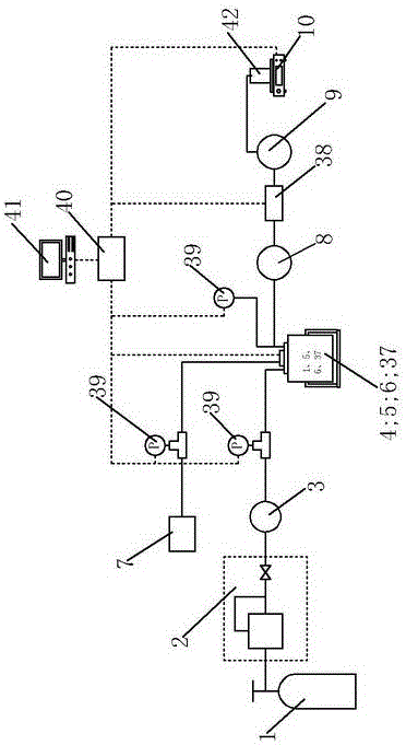
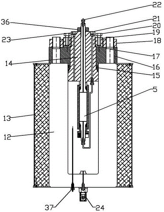
The invention discloses a device for testing permeability under high temperature and high pressure. The device can achieve test of the permeability of a rock sample under conditions of 50-500 DEG C and 0.2-100.0 Mpa. The device comprises a fluid source, a fluid supercharging device, a preheater, a high temperature high pressure reactor, a high temperature high pressure core holding unit, a transfusion pipeline, a confining press pump, a cooler, a backpressure control system, a precision balance and a data collection system. According to the device, real-time measurement on the permeability of the core under the conditions of high temperature and high pressure can be achieved, the device can be further used for simulating a transfusion process of the liquid in the rock in place under the ground, simulation study of underground in-situ exploiting such as underground hot gas exploiting, superheated steam exploiting and near / super critical fluid exploiting can be conducted, and new mentality and feasible testing programs can be provided for exploiting underground hot dry rock and thickened oil and in situ exploiting unconventional oil and gas resources such as oil sand and oil shale.

Description

technical field [0001] The invention relates to a high-temperature and high-pressure permeability testing device, in particular to a device capable of real-time testing of the permeability of a high-temperature and high-pressure fluid seepage inside a rock core. Background technique [0002] Rock permeability is an important parameter and index for reservoir physical property research, formation damage evaluation, and oil and gas reservoir exploitation design. The unconventional oil and gas resources that can be developed at present are mainly oil shale oil, coalbed methane, etc. The reservoirs of these unconventional oil and gas resources are tight, and the matrix porosity and permeability are low. Moreover, unconventional oil and gas resources need to be converted under high temperature and high pressure conditions, and it is difficult to form production capacity under normal circumstances. Under the infiltration of high-temperature and high-pressure fluids, the reservoir...

Claims


Application Information

Patent Timeline
Patent Type & Authority Applications(China)
IPC IPC(8): G01N15/08
CPCG01N15/0806G01N15/0826
Inventor 邓孙华何里孙友宏王洪艳王思远康世杰王永明
Owner JILIN UNIV
Learn More