Finless Microchannel Heat Exchanger

A micro-channel heat exchanger and fin technology, which is applied in heat exchange equipment, lighting and heating equipment, evaporator/condenser, etc., can solve the problem of reducing the side area of ​​heat exchange air and failing to ensure heat exchange area and heat exchange capacity and other problems, to achieve the effect of reducing the distance between flat tubes, shortening the defrosting time, and avoiding the reduction of heat transfer performance

Active Publication Date: 2022-03-15
SHANGHAI KELING ENERGY TECH
View PDF0 Cites 0 Cited by
  • Summary
  • Abstract
  • Description
  • Claims
  • Application Information

AI Technical Summary

Problems solved by technology

However, if the existing technology is used for processing, the minimum tube spacing of the obtained finless microchannel heat exchanger can only be reduced to 1 / 2 of the original, resulting in a significant reduction in the heat exchange air side area, and the same heat exchange cannot be guaranteed. area and heat transfer

Method used


Image

  • Finless Microchannel Heat Exchanger
  • Finless Microchannel Heat Exchanger
  • Finless Microchannel Heat Exchanger

Examples


Embodiment 1

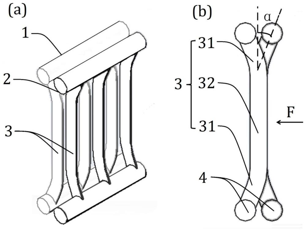
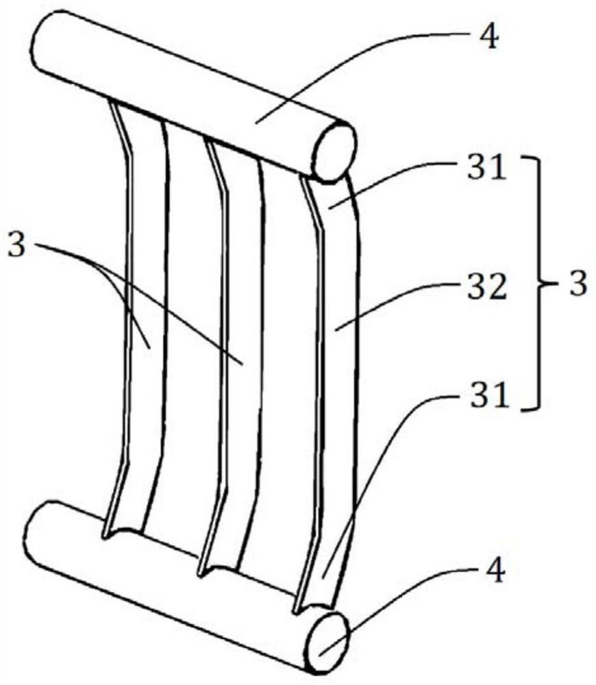
[0023] Such as figure 1 with figure 2 As shown, this embodiment includes a first heat exchange unit 1 and a second heat exchange unit 2 installed in combination, the first heat exchange unit 1 and the second heat exchange unit 2 are each provided with a number of C-shaped flat tubes 3, The C-shaped flat tube 3 includes a straight tube section 32 in the middle and bent sections 31 at both ends;

[0024] The C-shaped flat tubes 3 of the first heat exchange unit 1 and the C-shaped flat tubes 3 of the second heat exchange unit 2 are stacked alternately, and the middle straight tube sections 32 of the C-shaped flat tubes 3 are aligned in the width direction of the flat tubes, Form the effective heat transfer area of ​​the air side flow channel;

[0025] For the convenience of processing, the heat exchange units are processed separately first, and then assembled and installed. After the heat exchanger is assembled, the height and length of the headers 4 of the first heat exchange...


PUM


Abstract

A finless microchannel heat exchanger in the field of heat exchanger technology, comprising a combined first heat exchange unit and a second heat exchange unit, the first heat exchange unit and the second heat exchange unit are both set There are several C-shaped flat tubes, and the C-shaped flat tubes include a straight tube section in the middle and bent sections at both ends; the C-shaped flat tubes of the first heat exchange unit and the C-shaped flat tubes of the second heat exchange unit are stacked alternately Set, and the middle straight pipe section of the C-shaped flat pipe is aligned in the width direction of the flat pipe. The invention can avoid accumulation of dust layer and accumulation of water droplets on the basis of ensuring heat exchange performance, and shorten defrosting time.

Description

technical field [0001] The invention relates to a technology in the field of heat exchangers, in particular to a finless microchannel heat exchanger. Background technique [0002] Traditional microchannel heat exchangers include: headers, flat tubes and fins. Since the flat tubes and fins are close to vertical, and the fin spacing is small, only 1-2 mm, the microchannel heat exchanger is easily blocked by water droplets, frost and dust. When the flat tubes of the microchannel heat exchanger are placed horizontally, the surface of the flat tubes is easy to accumulate water and frost under low temperature conditions, and it is easy to accumulate dust in the outdoor environment; when the flat tubes of the microchannel heat exchanger are placed vertically, Frost is easy to accumulate on the fin surface under low temperature conditions, and dust is easy to accumulate under outdoor environment. [0003] Canceling the fin structure in the microchannel heat exchanger can solve the...

Claims


Application Information

Patent Timeline
Patent Type & Authority Patents(China)
IPC IPC(8): F25B39/00F28F1/02F28F19/00
CPCF25B39/00F28F1/02F28F19/00
Inventor 任滔吴国明赵定乾丁国良
Owner SHANGHAI KELING ENERGY TECH
Why Eureka
Try Eureka