A pump body assembly of a rolling rotor compressor
A rolling rotor type, compressor technology, applied in the field of compressors, can solve the problems of affecting the working performance of the compressor, high processing cost, high matching accuracy, and achieve the effects of low processing cost, low replacement cost, and fast drainage speed.
- Summary
- Abstract
- Description
- Claims
- Application Information
AI Technical Summary
Problems solved by technology
Method used
Image


Examples
Embodiment 1
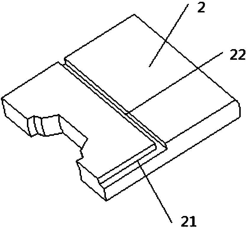
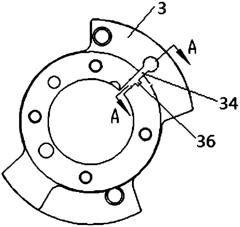
[0036] figure 1 Shown is the pump body assembly of the rolling rotor compressor described in this embodiment, which includes a cylinder 3, a roller 5, and a sliding plate 2. The cylinder 3 has a hollow cavity, and the hollow cavity is formed with radial penetration and suction. Gas port 32 and exhaust port 31, and the slide slot 34 formed between the suction port 32 and the exhaust port 31 and the spring hole 33 communicated with the slide slot 34; and a sealed cover The upper flange cover plate 1 and the lower flange cover plate 4 on both sides of the hollow cavity; the roller 5 is eccentrically installed in the hollow cavity, and its outer cylindrical surface is tangent to the inner wall of the hollow cavity The sliding piece 2 is slidably arranged in the sliding piece groove 34, one end of the sliding piece 2 closely fits with the roller 5, and the other end abuts against a spring fixedly arranged in the spring hole 33 at one end; The sliding piece 2 is formed with a drain...
Embodiment 2
[0038] The pump body assembly of the rolling rotor compressor in this embodiment includes a cylinder 3, a roller 5, and a sliding vane 2. The cylinder 3 has a hollow cavity, and the hollow cavity is formed with a radially penetrated suction port 32. And the exhaust port 31, and the slide slot 34 formed between the suction port 32 and the exhaust port 31 and the spring hole 33 communicated with the slide slot 34; and sealingly cover the The upper flange cover plate 1 and the lower flange cover plate 4 on both sides of the hollow cavity; the roller 5 is eccentrically installed in the hollow cavity, and its outer cylindrical surface is tangent to the inner wall of the hollow cavity; the sliding plate 2 is slidably arranged in the sliding piece groove 34, one end of the sliding piece 2 closely fits with the roller 5, and the other end abuts against a spring fixedly arranged in the spring hole 33; the hollow The cavity is formed with a drainage channel that connects the gap on the ...
Embodiment 3
[0040] The pump body assembly of the rolling rotor compressor in this embodiment includes a cylinder 3, a roller 5, and a sliding vane 2. The cylinder 3 has a hollow cavity, and the hollow cavity is formed with a radially penetrated suction port 32. And the exhaust port 31, and the slide slot 34 formed between the suction port 32 and the exhaust port 31 and the spring hole 33 communicated with the slide slot 34; and sealingly cover the The upper flange cover plate 1 and the lower flange cover plate 4 on both sides of the hollow cavity; the roller 5 is eccentrically installed in the hollow cavity, and its outer cylindrical surface is tangent to the inner wall of the hollow cavity; the sliding plate 2 is slidably arranged in the sliding piece groove 34, one end of the sliding piece 2 closely fits with the roller 5, and the other end abuts against a spring fixedly arranged in the spring hole 33; the hollow The cavity is formed with a drainage channel that connects the gap on the ...
PUM
 Abstract
Description
Claims
Application Information
 - R&D
- Intellectual Property
- Life Sciences
- Materials
- Tech Scout
- Unparalleled Data Quality
- Higher Quality Content
- 60% Fewer Hallucinations
Browse by: Latest US Patents, China's latest patents, Technical Efficacy Thesaurus, Application Domain, Technology Topic, Popular Technical Reports.
© 2025 PatSnap. All rights reserved.Legal|Privacy policy|Modern Slavery Act Transparency Statement|Sitemap|About US| Contact US: help@patsnap.com