Pulse coupling pump

A pulse coupling, pump body technology, applied in pulse balance, pump, pump device and other directions, can solve the problems of unstable measurement accuracy of liquid intake, increase of external volume and manufacturing cost, etc.

Active Publication Date: 2017-02-22
ZHEJIANG FAI ELECTRONICS
View PDF8 Cites 4 Cited by
  • Summary
  • Abstract
  • Description
  • Claims
  • Application Information

AI Technical Summary

Problems solved by technology

In this way, the overall volume and manufacturing cost of the pump are increased to a certain extent. In addition, the fluctuation of the liquid formed by

Method used


Image

  • Pulse coupling pump
  • Pulse coupling pump
  • Pulse coupling pump

Examples


Embodiment Construction

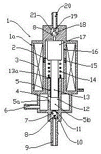
[0019] Such as figure 1 As shown, it is a schematic structural diagram of the first embodiment of the pulse coupling pump provided by the present invention. The pulse coupling pump 1 includes a pump body 1a and a low-pressure pump 2 therein, a high-pressure pump 12, a solenoid 3, a return spring 14, and Liquid channel 6, exhaust channel 20, infusion channel 9.

[0020] The low-pressure pump 2 includes an armature 17 , an armature sleeve 16 and a rectifying valve 21 . The armature 17 is located in the armature sleeve 16 and can move relative to the armature sleeve 16. The armature 17 and the armature sleeve 16 are formed of a magnetically conductive material, and the armature sleeve 16 is embedded with a magnetic gap 15 formed by non-magnetic conduction. , the front end of the armature 17 is located near the magnetic gap 15 . The rectification valve 21 is a ball valve that relies on pressure to open, including a rectification valve member 18, a rectification valve spring 19, ...


PUM


Abstract

A pulse coupling pump comprises a pump body, a low-pressure pump, a high-pressure pump and a solenoid, wherein the low-pressure pump, the high-pressure pump and the solenoid are arranged in the pump body. The low-pressure pump comprises an armature, an armature sleeve and a rectifying valve. The high-pressure pump comprises a plunger, a sleeve, an input valve and an output valve. The high-pressure pump and the low-pressure pump are coupled through the armature, that is, the armature is located in the armature sleeve and is driven by the magnetic field force of the solenoid to move in a reciprocating manner. On one hand, a plunger pump is driven to work, and on the other hand, bidirectional pulse liquid is formed, and forms directional flowing through the rectifying valve. The armature and the armature sleeve are formed by magnetic conduction materials, a non-magnetic-conduction magnetic gap is embedded in the armature sleeve, and the front end of the armature is located nearby the magnetic gap. The input valve is located on the upstream portion of directional liquid flow, when the input valve is opened, liquid passes through the input valve from the low-pressure pump to enter the high-pressure pump and is output through the output valve, and the output flow of the liquid is decided by driving force given by the solenoid.

Description

technical field [0001] The invention belongs to the field of liquid metering technology, especially the liquid injection metering technology related to engines, and specifically relates to engine fuel injection devices, engine exhaust purification nitrogen oxide selective catalytic reduction (SCR) systems, and diesel engine exhaust particulate matter filtration and collection (DPF) fuel injection regeneration system. Background technique [0002] Liquid metering technology is a basic technology that modern industry cannot do without. Its applications include: engine fuel injection system (including in-cylinder direct injection (GDI) and cylinder injection (MPI)), engine exhaust purification nitrogen oxide selective catalytic reduction (SCR) urea aqueous solution injection system, diesel exhaust particulate filter (DPF) regeneration injection system, etc., these systems have higher requirements for liquid metering. [0003] Taking the solenoid plunger pump device as an examp...

Claims


Application Information

Patent Timeline
IPC IPC(8): F04B17/04F04B13/00F04B23/06F04B11/00F04B53/10F04B53/06F01N3/28F02M59/10F01N3/025
Inventor 郗大光徐露明乐起奖杨延相
Owner ZHEJIANG FAI ELECTRONICS
Why Eureka
Try Eureka