A diesel engine installation frame integrating a fuel tank
A fuel tank and mounting frame technology, applied to locomotives with internal combustion engines, locomotives with gas turbines, locomotives, etc., can solve the problems of occupying space, increasing the weight of the whole vehicle, unfavorable locomotive pipelines and equipment layout, etc., to save installation space Effect
- Summary
- Abstract
- Description
- Claims
- Application Information
AI Technical Summary
Problems solved by technology
Method used
Image
Examples
Embodiment Construction
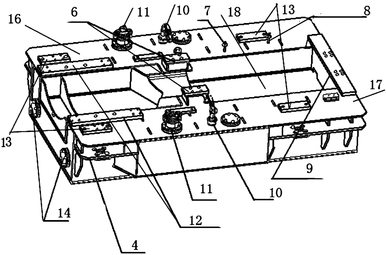
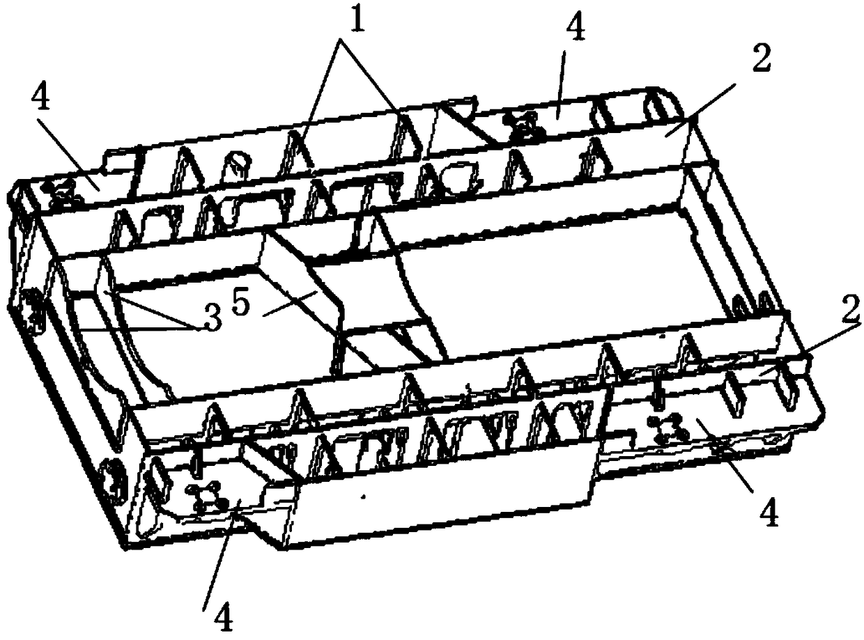
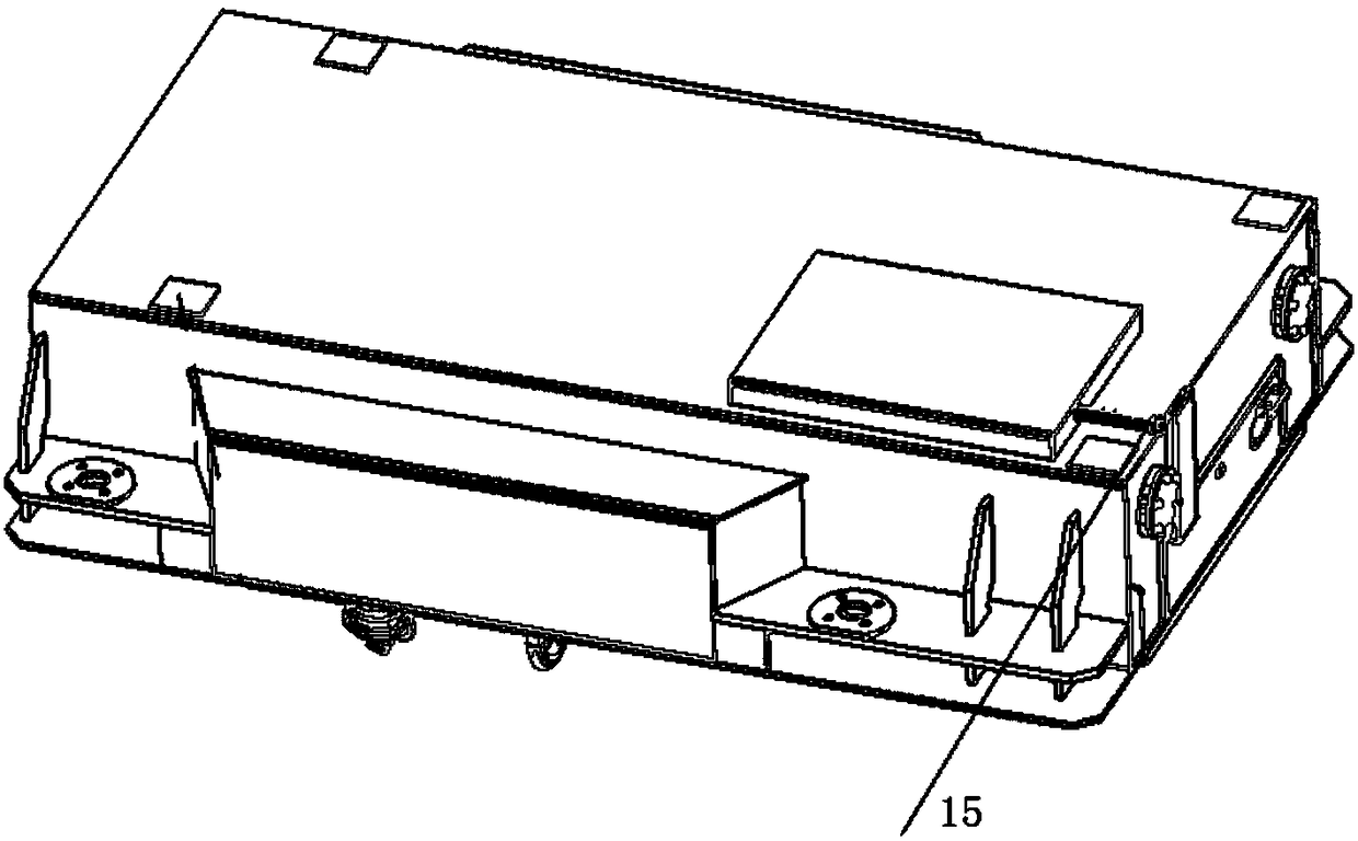
[0028] like figure 1 , 2 , 3, the present invention includes a base plate, the base plate has a first part of the fuel tank and a second part of the fuel tank that are oppositely arranged and communicated at the bottom, an oil sump between the first part of the fuel tank and the second part of the fuel tank, located at Mount the isolator mount 4 on the corner of the mount.
[0029] The first part of the fuel tank and the second part of the fuel tank together constitute the fuel storage space, and the oil collection tank is used to collect waste oil, waste water, etc. The structure of each part is explained below.
[0030] The first part of the fuel tank is a cavity, which is surrounded by the bottom plate area where it is located, side walls, and the first upper cover plate 16 . Inside the cavity are a longitudinal frame 2 arranged along the length direction of the mounting frame, and a number of transverse frames 1 arranged along the width direction of the mounting frame. ...
PUM
 Abstract
Description
Claims
Application Information
 - R&D
- Intellectual Property
- Life Sciences
- Materials
- Tech Scout
- Unparalleled Data Quality
- Higher Quality Content
- 60% Fewer Hallucinations
Browse by: Latest US Patents, China's latest patents, Technical Efficacy Thesaurus, Application Domain, Technology Topic, Popular Technical Reports.
© 2025 PatSnap. All rights reserved.Legal|Privacy policy|Modern Slavery Act Transparency Statement|Sitemap|About US| Contact US: help@patsnap.com


