
Rear floor assembly reversing tooling vehicle

A technology for turning over the assembly and the rear floor, which is applied to the direction of the workbench, auxiliary devices, manufacturing tools, etc., can solve the problems of poor control of manual turning force, poor turning stability, bump damage of the rear floor assembly, etc., to achieve convenient and stable laying The effect of solder joint or solder joint quality inspection

Inactive Publication Date: 2017-02-22
安徽新大洋汽车配件有限公司
View PDF8 Cites 3 Cited by
  • Summary
  • Abstract
  • Description
  • Claims
  • Application Information

AI Technical Summary

Problems solved by technology

The existing rear floor assembly vehicle can only be used for placing the rear floor assembly, and the turning of the rear floor assembly depends on at least two operators standing at both ends or both sides of the rear floor assembly vehicle and flipping back and forth to reach the rear floor assembly. Assembly welding and testing, this kind of manual overturning consumes a lot of manpower, and the manual overturning force is not easy to control, and the overturning stability is poor, especially when the operator operates for a long time, there is insufficient physical strength to cause the rear floor assembly to fall off during the overturning, resulting in the rear floor The assembly was bumped and damaged, and even hit the operator with his hand, causing an accident

Method used


Image

  • Rear floor assembly reversing tooling vehicle
  • Rear floor assembly reversing tooling vehicle
  • Rear floor assembly reversing tooling vehicle

Examples


Embodiment Construction

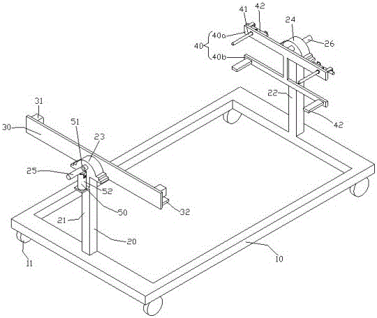
[0014] Referring to the drawings, a rear floor assembly turning tooling vehicle includes a chassis 10 and a bracket 20 mounted on the chassis 10. The bracket 20 includes a first and a second parallel standing at the front and rear ends of the chassis 10 Two supporting rods 21, 22, the top ends of the first and second supporting rods 21, 22 are symmetrically provided with first and second bearing seats 23, 24, and the first bearing seat 23 is provided with a first rotating shaft 25, The first rotating shaft 25 is located on the inner side of the first bearing seat 23 and is fixedly connected with a first limiting plate 30. On the first limiting plate 30, two block pins 31 are symmetrically provided with the first rotating shaft 25 as a symmetrical axis. A first support plate 32 is symmetrically provided on the position plate 30 below the block pin 31, a second rotation shaft 26 is provided on the second bearing seat 24, and the second rotation shaft 26 is located inside the secon...


PUM


Abstract

The invention relates to a rear floor assembly reversing tooling vehicle which comprises a chassis and a support erected on the chassis. The support comprises a first supporting rod and a second supporting rod, wherein the first supporting rod and the second supporting rod are located at the front end and the rear end of the chassis correspondingly and vertically arranged in parallel. A first bearing seat and a second bearing seat are symmetrically arranged at the top end of the first supporting rod and the top end of the second supporting rod correspondingly. A first rotary shaft is arranged on the first bearing seat. The portion, located on the inner side of the first bearing seat, of the first rotary shaft is fixedly connected with a first limiting plate. Two square pins are symmetrically arranged on the first limiting block with the first rotary shaft as the symmetry axis. First supporting plates are symmetrically arranged on the first limiting plate and located below the square pins. The second bearing seat is provided with a second rotary shaft. The portion, located on the inner side of the second bearing seat, of the second rotary shaft is fixedly connected with a second limiting plate. Two cylindrical pins are symmetrically arranged on the second limiting plate with the second rotary shaft as the symmetry axis. Second supporting plates are symmetrically arranged on the second limiting plate and located below the cylindrical pins. Tools are reversed stably, and welding spot positioning of a rear floor assembly and welding spot quality detection are facilitated.

Description

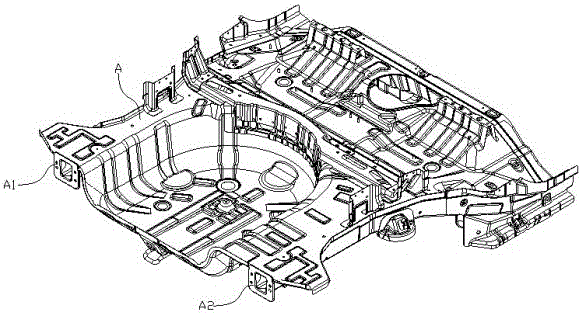
Technical field [0001] The invention belongs to the field of vehicle production and manufacturing, and relates to the production and manufacturing of passenger car body-in-white, in particular to a rear floor assembly turning tooling vehicle. Background technique [0002] The rear floor assembly is a plate welded to the rear part of the car floor. Its function is mainly to install the rear seats and store the spare tire. Refer to figure 1 It mainly includes left and right anti-collision beams A1 and A2 arranged on the left and right sides of the rear floor assembly A and sheet metal parts placed on the left and right anti-collision beams A1 and A2. When the rear floor assembly A is welded, it needs to be flipped up and down several times to achieve the purpose of welding joints on the front and back of the rear floor assembly A, and after the solder joints are finished, they must be turned up and down to check the quality of the solder joints. After passing the inspection, the re...

Claims


Application Information

Patent Timeline
IPC IPC(8): B25H1/18B23K37/047
CPCB23K37/047B25H1/0007B25H1/18
Inventor 宣宏范曙光
Owner 安徽新大洋汽车配件有限公司
Learn More