A fillet weld automatic welding control method based on laser displacement sensor

A laser displacement, automatic welding technology, applied in welding equipment, manufacturing tools, arc welding equipment, etc., to achieve the effects of uniformity and stability, fast output response, and simplified structure

Active Publication Date: 2019-05-10
XIANGTAN UNIV
View PDF2 Cites 0 Cited by
  • Summary
  • Abstract
  • Description
  • Claims
  • Application Information

AI Technical Summary

Problems solved by technology

[0003] In order to solve the deficiencies of existing methods or technologies and better promote the development of automatic welding, a laser displacement sensor automatic welding control method for fillet welds is provided, which is used for fillet weld tracking and fillet weld slope in automatic welding machines. Port recognition and automatic adjustment of welding parameters

Method used


Image

  • A fillet weld automatic welding control method based on laser displacement sensor
  • A fillet weld automatic welding control method based on laser displacement sensor
  • A fillet weld automatic welding control method based on laser displacement sensor

Examples


Embodiment 1

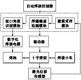
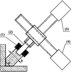
[0028] Embodiment 1: The system block diagram of the fillet weld automatic welding control method of a kind of laser displacement sensor of the present invention is as follows figure 1 As shown, the system includes: laser displacement sensor, automatic welding controller, driver, cross carriage, digital welding power supply, welding torch, welding trolley, among which, the automatic welding controller includes data sampling module, weld seam deviation detection module, groove angle Identification module; using laser displacement sensor to sense the displacement of the fillet weld groove; using the data sampling module to sample the output signal of the laser displacement sensor; the weld deviation detection module uses the three harmonic decoupling algorithm to detect the fillet weld The longitudinal deviation of the fillet weld is detected by the shape filter threshold method; the groove angle identification module adopts the double harmonic decoupling algorithm to identify th...

Embodiment 2

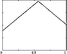
[0061] Embodiment 2: Through the method of the present invention, the laser displacement sensor is used to sense the displacement of the fillet weld groove, and the data sampling module is used to perform data sampling on the output signal of the laser displacement sensor. The sense signal sampling waveform is as Figure 7 As shown, the lateral deviation e of the fillet weld is detected by the three-harmonic decoupling algorithm through the weld deviation detection module, Figure 8 is the waveform diagram of the laser displacement sensing signal obtained after calculation when the fillet weld deviates to the left, and then uses the morphological filter threshold method to detect the longitudinal deviation y of the fillet weld. k)(k=0,1,2...N-1) such as Figure 9 As shown in the shaded area in the middle, the shape threshold H of the laser displacement sensing signal of the fillet weld is as follows Figure 10 As shown, through the groove angle identification module, the dou...


PUM


Abstract

The invention discloses an automatic fillet weld welding control method and device for a laser displacement sensor. The method and the device are used for fillet weld tracking, fillet weld groove recognizing and automatic welding parameter adjusting of a special automatic welding machine. A system adopted in the method adopts the laser displacement sensor to carry out displacement sensing on a fillet weld groove, and an automatic welding controller is utilized for carrying out data sampling on signals output by the laser displacement sensor; in the weld deviation detection process, for sampled data, a three-harmonic decoupling algorithm is adopted for detecting fillet weld lateral deviation, a morphological filtering threshold value method is adopted for detecting fillet weld longitudinal deviation, and according to the weld deviation, a cross-shaped sliding frame is driven to adjust the position of a welding gun; and when the fillet weld groove is recognized, a double-harmonic decoupling algorithm is adopted for recognizing the angle of the fillet weld groove, and according to the angle of the groove, working parameters of a digitalized welding power source are adjusted automatically. By the adoption of the method, the fillet weld deviation can be accurately detected, the angle of the fillet weld groove can be recognized, the welding parameters can be adjusted automatically, and automatic welding efficiency and quality are improved.

Description

technical field [0001] The invention relates to the field of automatic welding, in particular to an automatic welding control method for fillet welds with a laser displacement sensor. Background technique [0002] Welding automation and intelligence have become the development trend of welding technology and an important guarantee for improving welding quality and welding efficiency. In the welding production of rail transit, marine engineering equipment, heavy machinery, shipping and other industries, many welding structures are still in the stage of manual welding or semi-automatic welding due to their complex structure and various types of weld seam specifications. The production efficiency is low and the working environment is poor. In actual welding production, due to workpiece processing or assembly errors, the welding torch deviates from the center of the weld seam, and it is necessary to dynamically adjust the position of the welding torch and welding parameters. Th...

Claims


Application Information

Patent Timeline
Patent Type & Authority Patents(China)
IPC IPC(8): B23K9/095B23K9/127
CPCB23K9/0953B23K9/1274
Inventor 尹力洪波李毅张贤锌
Owner XIANGTAN UNIV
Why Eureka
Try Eureka