Motor vehicle electropneumatic spring energy storage brake with a jumpy pressure rise when the brake is released

An energy storage braking, motor vehicle technology, applied in the direction of braking transmission, braking action starting device, hydraulic braking transmission, etc., can solve problems such as unfavorable dynamics

Active Publication Date: 2019-03-01
KNORR-BREMSE SYST FUER NUTZFAHRZEUGE GMBH
View PDF7 Cites 0 Cited by
  • Summary
  • Abstract
  • Description
  • Claims
  • Application Information

AI Technical Summary

Problems solved by technology

[0007] However, it is problematic in such spring-loaded brake cylinders that in order to counteract the action of the stored-energy spring for brake release by filling the spring-charged brake chamber with air, certain frictional effects must first be overcome. Breakaway force until the spring-loaded brake piston can move into the brake release position, which can lead to unfavorable dynamics in the context of e.g. pressure-regulated auxiliary braking

Method used


Image

  • Motor vehicle electropneumatic spring energy storage brake with a jumpy pressure rise when the brake is released
  • Motor vehicle electropneumatic spring energy storage brake with a jumpy pressure rise when the brake is released
  • Motor vehicle electropneumatic spring energy storage brake with a jumpy pressure rise when the brake is released

Examples


Embodiment Construction

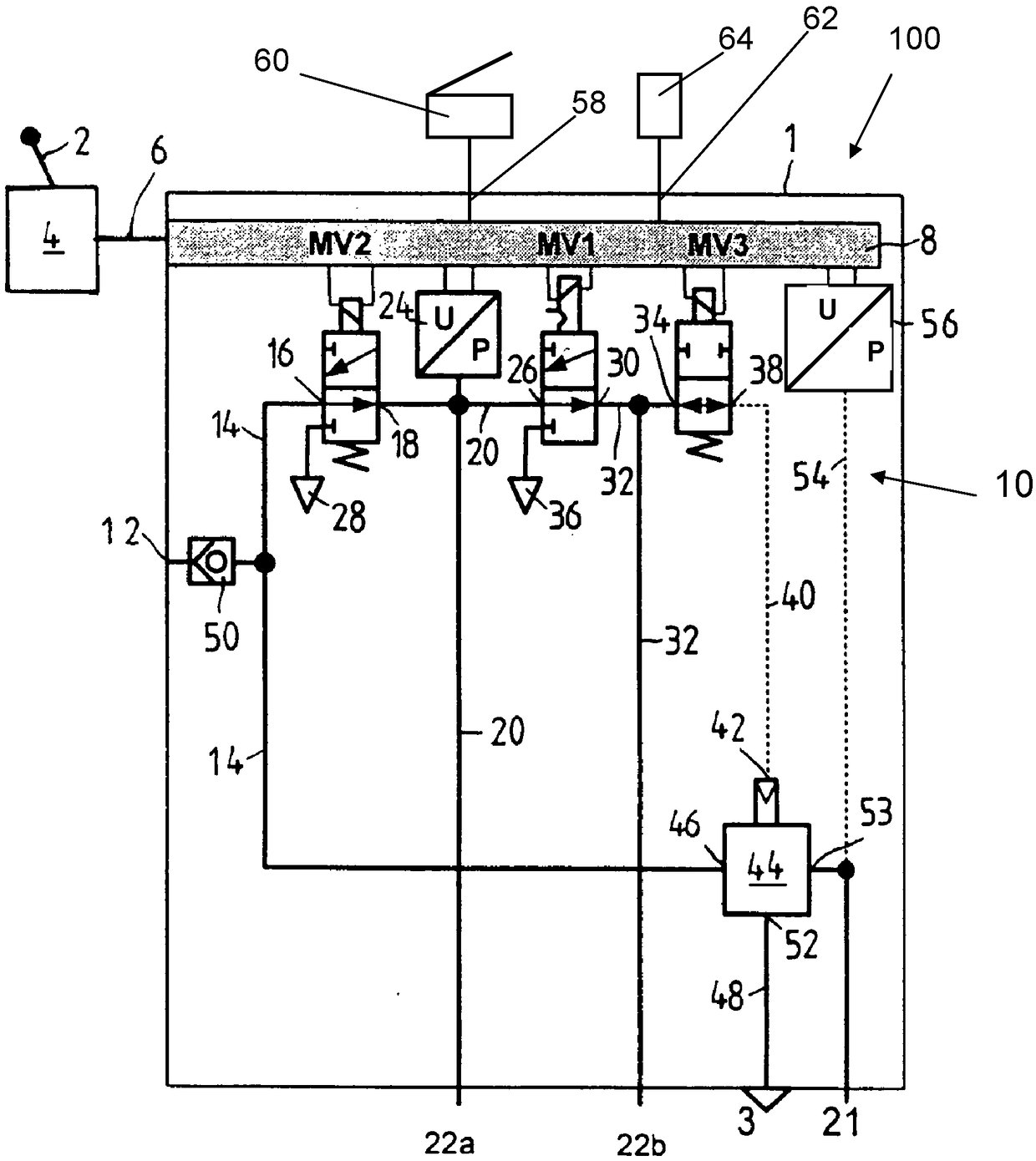
[0047] The electro-pneumatic parking brake device 100 figure 1 The preferred embodiment shown in is part of a brake device of a pressure medium operated, for example an electrically operated tractor-trailer combination, and is arranged in the tractor. This particularly relates to an electronically regulated braking system (EBS).

[0048] The electro-pneumatic parking brake device 100 includes a parking brake module 1 symbolically shown by a box and a parking brake signal transmitter 4, which is manually operated, for example, by a brake operating mechanism Here, for example, it is adjusted via the operating lever 2, and the parking brake signal transmitter controls the electronic control device 8 of the parking brake module 1 through the electronic signal wire 6 with electrical operating signals.

[0049] Preferably, the electronic control device 8 is integrated into the parking brake module 1. In addition, a solenoid valve device 10 that can be controlled by the control device 8 ...


PUM


Abstract

The invention relates to an electro-pneumatic spring energy storage brake device (1) for a motor vehicle, comprising means for generating an electric brake operating signal (the electric brake operating signal represents at least "brake applied" and "brake applied"). device, the electronic control device (8) receiving the brake operation signal, the electropneumatic valve device (10) controlled by the control electronic device (8) according to the operation signal, and at least one pneumatically operated spring storage An energy braking cylinder, wherein the electro-pneumatic valve device (10) is connected to a compressed air source (12) to inflate the at least one spring energy storage brake cylinder or ventilated by connecting to a pressure relief port (3) , and wherein there is a maximum inflation state of the electropneumatic valve device (10) that can be caused by the electronic control device (8), in which state the electropneumatic valve device (10) opens at the compression The largest flow cross-section between the air source (12) and the at least one spring-charged cylinder. It is provided according to the invention that the electronic control unit (8) is configured such that the solenoid valve unit (10) is activated by the The electronic control unit (8) is controlled in the maximum charging state for a long time in this way until the pressure in at least one spring storage brake cylinder starts from the output pressure value with a first gradient and jumps to a level higher than that At a first pressure value that is higher, but still below the brake release pressure for fully releasing the spring-loaded brake cylinder, and is controlled in a state after reaching the first pressure value, In this state, starting from a first pressure value, the pressure in at least one spring accumulator brake cylinder is increased with a second gradient, which is smaller than the first gradient, to At a second pressure value higher than the first pressure value.

Description

Technical field [0001] The present invention starts from the electric dynamic spring energy storage braking device of a motor vehicle. The electric dynamic spring energy storage braking device includes an electric brake for generating at least the states of "brake compression" and "brake release". An operating signal device, an electronic control device that receives the brake operating signal, an electric valve device controlled by the control electronic device according to the operation signal, and at least one pneumatically operated spring energy storage brake cylinder, wherein the electric valve device At least one spring energy storage brake cylinder is inflated by connecting with a compressed air source, and is ventilated by connecting with a pressure reducing port, and among them, there is an electric valve device that can be caused by the electronic control device. In the inflated state, in the maximum inflated state, the electrically operated valve device opens the larg...

Claims


Application Information

Patent Timeline
Patent Type & Authority Patents(China)
IPC IPC(8): B60T13/66B60T13/74
CPCB60T13/662B60T13/683B60T13/743B60T7/107B60T11/10B60T13/24B60T13/26B60T13/38B60T13/385B60T13/66B60T13/68B60T13/70B60T13/74B60T15/02B60T15/027B60T17/08B60T17/18B60T8/248B60T8/327
Inventor M·赫格斯S·黑格R·魏兰M·克卢钦斯基
Owner KNORR-BREMSE SYST FUER NUTZFAHRZEUGE GMBH
Why Eureka
Try Eureka