Method for producing a camshaft assembly

A technology of camshafts and cam components, which is applied to cams, couplings, engine components, etc., and can solve problems such as low precision

Active Publication Date: 2017-02-15
THYSSENKRUPP PRESTA TECCENTER AG
View PDF12 Cites 0 Cited by
  • Summary
  • Abstract
  • Description
  • Claims
  • Application Information

AI Technical Summary

Problems solved by technology

The widened area used to form the cam seat is produced using a mandrel tool, whereby only low precision can be achieved

Method used


Image

  • Method for producing a camshaft assembly
  • Method for producing a camshaft assembly
  • Method for producing a camshaft assembly

Examples


Embodiment Construction

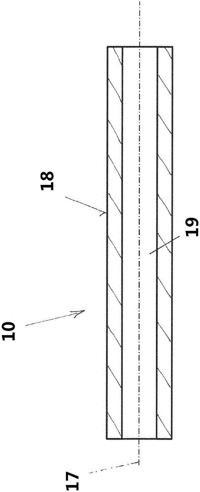
[0031] figure 1Exemplarily shown is a carrier shaft 10 with a non-grinding surface 18 , wherein the carrier shaft 10 is in the form of a hollow shaft and comprises a cavity 19 extending along a central axis 17 . The carrier shaft 10 thus forms a weight-minimized tube extending rotationally symmetrically with respect to the central axis 17 and the carrier shaft 10 can be cut to length, for example, from a rod of material.

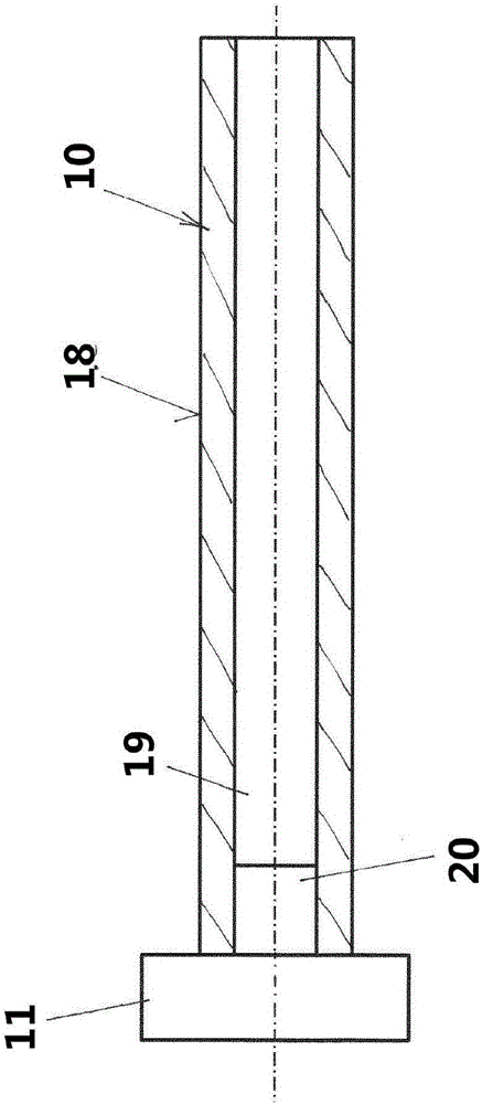
[0032] figure 2 An assembly consisting of a carrier shaft 10 and an end piece 11 is shown, and the end piece 11 may for example be a drive wheel, a phase adjuster or part of a phase adjuster, and in the context of the present invention the end piece 11 is Have part of the camshaft ready for use. For fastening the end part 11, the end part 11 comprises a protrusion 20, which can be inserted, for example, into the cavity 19 of the carrier shaft 10, wherein the end part 11 can also be connected in some other way, for example by an adhesive bonding process. ...


PUM


Abstract

The present invention relates to a method for producing a ready-for-use camshaft (1) for controlling valves of an internal combustion engine, comprising a carrier shaft (10), on which an end component (11), for example a drive wheel, a phase shifter or a portion of a phase shifter, is arranged, and comprising a plurality of cam elements (12) which are affixed to the carrier shaft (10) in a fixed position, wherein the method comprises at least the following steps: a) providing the carrier shaft (10) and the end component (11), b) joining the end component (11) to the carrier shaft (10), c) grinding at least the carrier shaft (10) in order to form cam seats (13) so that it is ready for use, d) forming a surface profile (14) in a first cam seat (13), e) providing a cam element (12) having ready-for-use properties, f) seating the cam element (12) on the cam seat (13) provided with the surface profile (14), and g) repeating steps d) to f) with a frequency corresponding to a required number of cam elements (12).

Description

technical field [0001] The invention relates to a method for producing a ready-to-use camshaft for controlling valves of an internal combustion engine, said camshaft having a carrier shaft on which an end is arranged and a plurality of cam elements part, an end part such as a drive wheel, a phaser, or a part of a phaser, the plurality of cam elements are attached to the carrier shaft in a positionally fixed manner. Background technique [0002] A method for producing ready-to-use camshafts is known, for example, from WO 2012 / 031770 A1, wherein, in order to join a plurality of cam elements to the carrier shaft, cooling of the carrier shaft and heating of the cam elements are carried out, This enables the carrier shaft to be pushed through the bore of the camshaft. The carrier shaft is then reheated and the cam element is cooled again. As a result, the cam element is fastened on the carrier shaft by means of an interference fit, which occurs due to thermal changes in shape. ...

Claims


Application Information

Patent Timeline
Patent Type & Authority Applications(China)
IPC IPC(8): B23P11/00
CPCB23P11/00B24B19/12B23P2700/02F01L2001/0471F16D1/072F01L2303/00F01L1/047F01L1/34F16D1/06F16H53/025
Inventor 曼弗雷德·穆斯特尔马尔科·丘尔利奇亚伦·费舍尔彼得·维斯纳尼古拉斯·霍利维克约尔格·沙特兹尔马提亚尔·丹特斯拉斐尔·霍贝尔
Owner THYSSENKRUPP PRESTA TECCENTER AG
Why Eureka
Try Eureka