
Motor rotor and motor having motor rotor and compressor

A motor rotor and rotor technology, which is applied in the direction of electric components, electrical components, electromechanical devices, etc., can solve the problems of large angle range of cutting angle, unlimited size of cutting angle, and limited effect, so as to weaken the motor cogging torque and rotation speed. The effects of torque ripple, improved stability and reliability, and no reduction in motor efficiency

Active Publication Date: 2017-02-15
GREE ELECTRIC APPLIANCES INC
View PDF8 Cites 6 Cited by
  • Summary
  • Abstract
  • Description
  • Claims
  • Application Information

AI Technical Summary

Problems solved by technology

[0003] Patent CN104600938B reduces the torque ripple of the motor by setting chamfers at the end of the magnetic steel slot, but the effect is limited, and the position is not limited. If the position is changed, it may not be effective; similarly, the patent CN105846558A has restrictions on the cutting angle of the magnetic steel slot , the 9-slot 6-pole motor described in this patent document has a too large range of cutting angles, and the size of the cutting angle is not limited, which affects the use effect
The above patents do not effectively limit the cutting angle of the magnetic steel groove, and cannot achieve the required use effect

Method used


Image

  • Motor rotor and motor having motor rotor and compressor
  • Motor rotor and motor having motor rotor and compressor
  • Motor rotor and motor having motor rotor and compressor

Examples


Embodiment Construction

[0029] The present invention is described below based on examples, but the present invention is not limited to these examples.

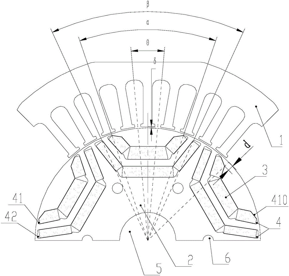
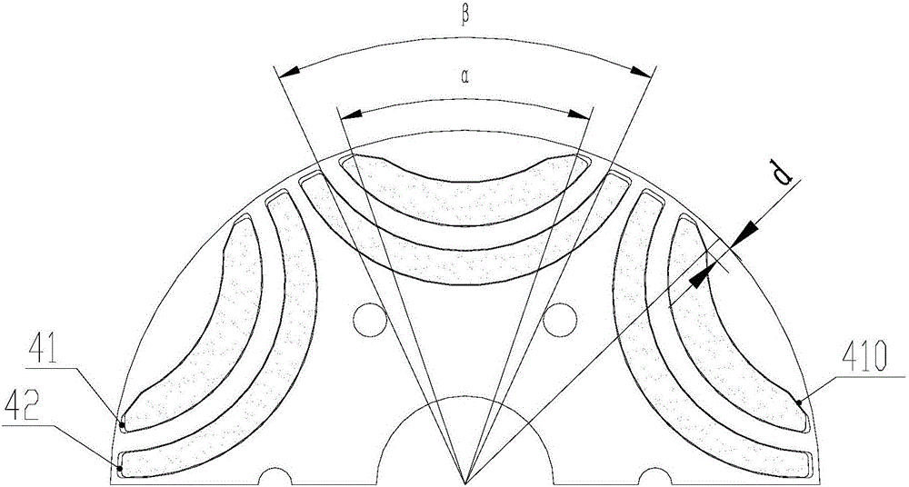
[0030] Such as Figure 1-3 As shown, the first aspect of the present invention provides a motor rotor, preferably a permanent magnet synchronous reluctance motor rotor, which includes a rotor core 2 and a rotating shaft (not shown), etc., the rotor core 2 is provided with a magnet 3 (preferably permanent magnet, such as the magnet groove 4 of magnetic steel). In the preferred embodiment shown in the figure, the rotor core 2 is further provided with a connecting hole 6 and a shaft hole 5 for matching with a rotating shaft.

[0031] figure 1 Also shows a part of the iron core 1 of the stator matched with the motor rotor, wherein an air gap is formed between the stator and the rotor, and the width of the air gap is denoted as δ; at the same time, the stator includes teeth uniformly arranged along the circumferential direction Slots (that is, winding ...


PUM


Abstract

The invention provides a motor rotor and a motor having the motor rotor and a compressor. The motor rotor comprises a rotor iron core which is provided with magnet slots used for placing magnets. The magnet slot of each pole of the motor rotor comprises a first magnet slot. The first magnet slot is provided with a first slot wall and a second slot wall. The first slot wall is arranged at the radially external side relative to the second slot wall. The two ends of the first slot wall are provided with first cut corners. The radial distance d from the internal vertex of the first cut corners to the excircle of the rotor iron core meets 3*delta<=d<=7*delta, wherein delta is the air gap width between the motor rotor and the matched stator. According to the motor rotor, the motor tooth slot torque and torque ripples can be effectively weakened so that the electromagnetic force of the motor can be reduced, the vibration noise of the motor can be reduced and the operation stability and reliability of the motor can be enhanced.

Description

technical field [0001] The invention relates to the technical field of motors, in particular to a motor rotor and a motor and a compressor with the same. Background technique [0002] At present, permanent magnet motors are more and more widely used, requiring high motor efficiency and low energy consumption; small motor torque ripple, easy for system control, and reliable and stable operation; small vibration and noise, meeting user comfort requirements. [0003] Patent CN104600938B reduces the torque ripple of the motor by setting chamfers at the end of the magnetic steel slot, but the effect is limited, and the position is not limited. If the position is changed, it may not be effective; similarly, the patent CN105846558A has restrictions on the cutting angle of the magnetic steel slot , The 9-slot 6-pole motor described in this patent document has a too large angle range of the cutting angle, and the size of the cutting angle is not limited, which affects the use effect....

Claims


Application Information

Patent Timeline
IPC IPC(8): H02K1/22H02K1/27H02K1/16
CPCH02K1/165H02K1/223H02K1/276
Inventor 史进飞吴曼肖勇米泽银陈彬
Owner GREE ELECTRIC APPLIANCES INC
Learn More