
Production method for depletion mode power transistor

A technology for power transistors and manufacturing methods, which is applied in semiconductor/solid-state device manufacturing, semiconductor devices, electrical components, etc., and can solve problems such as inapplicability to depletion-mode VDMOS

Inactive Publication Date: 2017-02-15
深圳深爱半导体股份有限公司
View PDF4 Cites 3 Cited by
  • Summary
  • Abstract
  • Description
  • Claims
  • Application Information

AI Technical Summary

Problems solved by technology

Since there is no depletion layer in the enhanced VDMOS, P well (P-) implantation, N+ implantation and P+ implantation can be performed after the polycrystalline manufacturing, but due to the existence of the depletion layer, this manufacturing process is not suitable for depletion Type VDMOS Fabrication

Method used


Image

  • Production method for depletion mode power transistor
  • Production method for depletion mode power transistor
  • Production method for depletion mode power transistor

Examples


Embodiment Construction

[0024] In order to facilitate the understanding of the present invention, the present invention will be described more fully below with reference to the associated drawings. A preferred embodiment of the invention is shown in the drawings. However, the present invention can be embodied in many different forms and is not limited to the embodiments described herein. Rather, these embodiments are provided so that the disclosure of the present invention will be thorough and complete.

[0025] Unless otherwise defined, all technical and scientific terms used herein have the same meaning as commonly understood by one of ordinary skill in the technical field of the invention. The terms used herein in the description of the present invention are for the purpose of describing specific embodiments only, and are not intended to limit the present invention. As used herein, the term "and / or" includes any and all combinations of one or more of the associated listed items.

[0026] The se...


PUM


Abstract

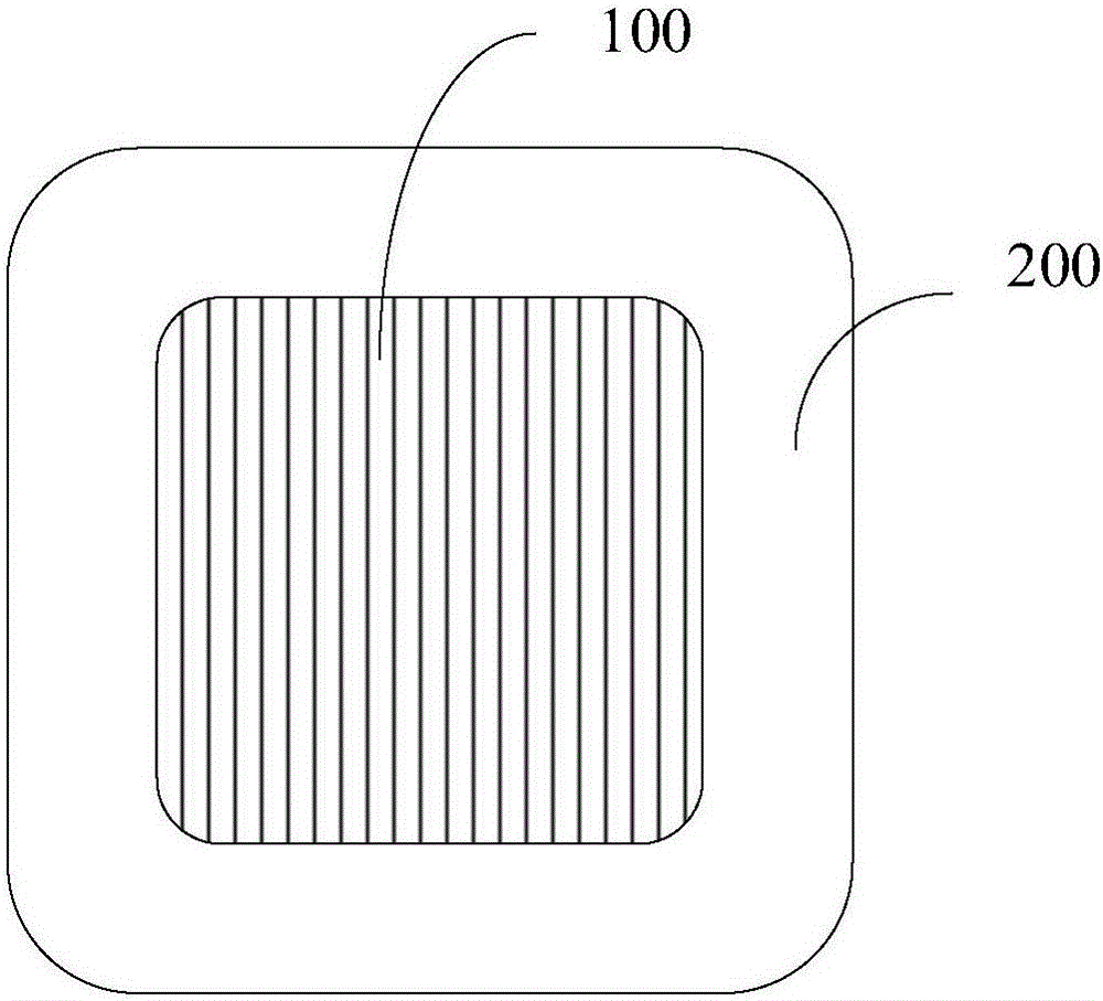
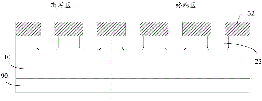
The invention relates to a production method for a depletion mode power transistor. The method comprises the steps of forming field oxide layers on a first conductive type substrate on a front face of a wafer; carrying out second conductive type photoetching and etching; injecting second conductive type ions and forming second conductive type areas in the first conductive substrate; growing second field oxide layers on the front face of the wafer; carrying out second conductive type well photoetching and etching; injecting the second conductive type ions and forming second conductive type wells at two sides of the second conductive type areas; carrying out depletion layer photoetching and etching; injecting first conductive type ions and forming depletion layers at two sides of the second conductive type areas; forming polycrystalline silicon gates and polycrystalline silicon field plates on the front face of the wafer; and carrying out self-alignment injection on the first conductive type ions by taking the polycrystalline silicon gates and the second field oxide layers as masks, and forming first conductive type areas in the second conductive type wells. According to the method, through utilization of the second field oxide layers as the masks for carrying out the self-alignment injection on the first conductive type ions, a photoetching process can be eliminated.

Description

technical field [0001] The invention relates to the field of semiconductor manufacturing, in particular to a manufacturing method of a depletion power transistor. Background technique [0002] Field effect transistors are divided into depletion mode and enhancement mode. The depletion type field effect transistor has a channel at zero gate bias and can conduct electricity; the enhancement mode field effect transistor does not have a channel at zero gate bias and cannot conduct electricity. The turn-on voltage V of a depletion-mode N-channel MOSFET (metal oxide semiconductor field effect transistor) TH is a negative value, the V of the enhancement mode N-channel MOSFET TH is a positive value. [0003] In the depletion mode MOSFET, the impurity concentration doped to the channel is changed during the manufacturing process, so that the conductive channel exists even if the gate is not applied with voltage. If one wants to turn off the channel, a negative voltage must be app...

Claims


Application Information

Patent Timeline
IPC IPC(8): H01L21/331H01L21/336
CPCH01L29/66712
Inventor 李学会
Owner 深圳深爱半导体股份有限公司
Learn More