


Quick Research
Generate reliable direction feasibility study reports for your R&D in just a few steps.

Technical Q&A
Discover and master advanced knowledge NOW. Basics, ideas, possibilities, all at once.

Find Solutions
As an expert in R&D theories, this can generate solutions to your technical problems instantly.

Evaluate Feasibility
Analyze your overall solution with one click, know your potential R&D risks in advance.

Monitor Landscape
Get weekly tech updates, stay abreast of the latest tech innovations and key insights.
Novel heat exchanger core
A heat exchanger and core technology, used in heat exchange equipment, lighting and heating equipment, damage protection and other directions, can solve the problems of reducing the service life of heat exchangers, high requirements for fluid working fluid cleanliness, scaling, etc. Achieve the effect of reducing requirements, solving the requirements of easy scaling or blockage due to excessive particle diameter in the working medium, and reducing the cleanliness of the fluid working medium
- Summary
- Abstract
- Description
- Claims
- Application Information
AI Technical Summary
Problems solved by technology
Method used
Image

Examples
Embodiment 1
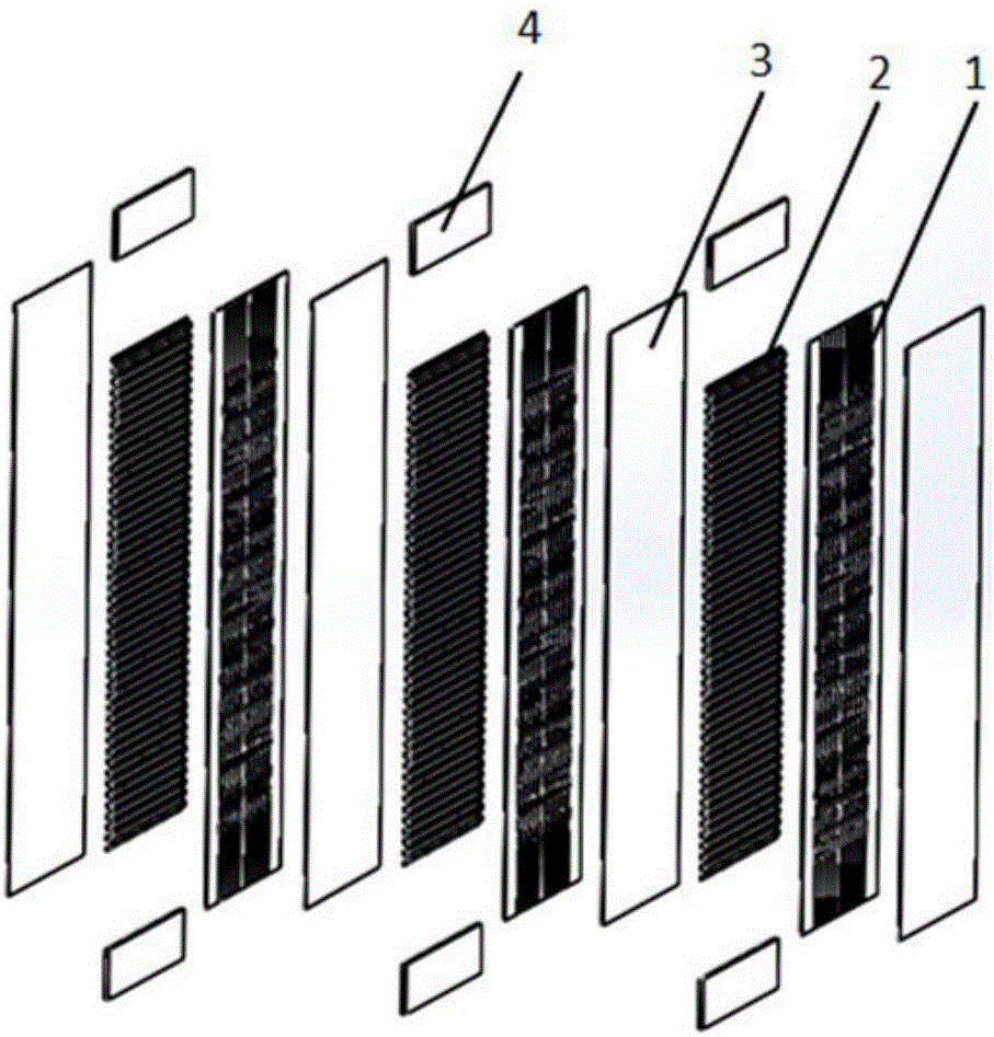
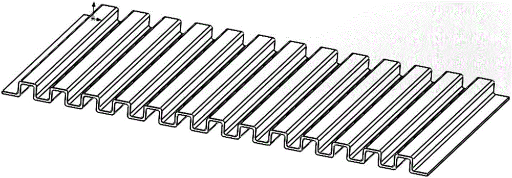
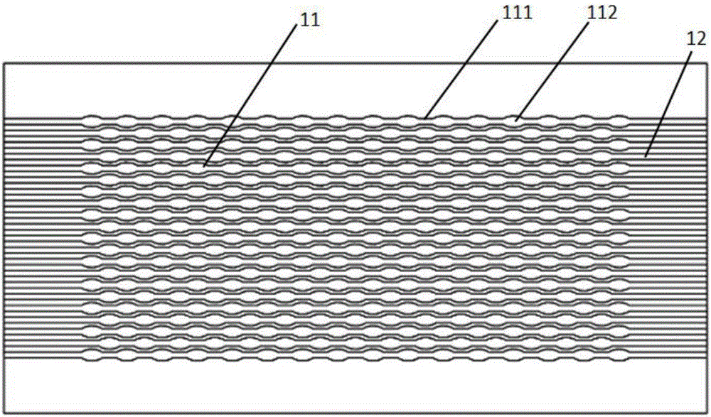
[0048] combine Figure 1-4 , this embodiment provides a new type of heat exchanger core, including an etched plate 1, a forming plate 2 and a partition 3; the etched plate 1 is etched with heat exchange flow channels 11; the heat exchange flow channels 11 are composed of alternately arranged straight channels 111 and elliptical channel 112, wherein: the straight channel 111 communicates with the elliptical channel 112; the major axis of the elliptical channel 112 and the central axis of the direct channel 111 along the liquid flow direction are on the same straight line; n Etched plates 1 and m shaped plates 2 are placed alternately, where n≥1, m≥1, m and n are both positive integers; partitions 3 are provided between the etched surfaces of adjacent etched plates 1 and formed plates 2 . Both m and n are 1.
[0049] The multiple straight channels 111 and the elliptical channels 112 form a tapering and expanding structure.
[0050] One side of the etched plate 1 is etched with...
Embodiment 2
[0058] The direct-flow channel 111 is a parallel channel with a width of 2 mm; the oval flow channel 112 has a long axis of 10 mm and a short axis of 4 mm; the distance between the centers of two adjacent oval flow channels 112 is 15 mm; The distance between the central axes of the heat exchange channels 11 along the fluid flow direction is 3 mm.
Embodiment 3
[0060] The straight-flow channel 111 is a parallel channel with a width of 10 mm; the major axis of the oval channel 112 is 30 mm, and the minor axis is 15 mm; the distance between the centers of two adjacent oval channels 112 is 50 mm; the adjacent The distance between the central axes of the two heat exchange channels 11 along the fluid flow direction is 15 mm.
PUM
| Property | Measurement | Unit |
|---|---|---|
| Width | aaaaa | aaaaa |
| Width | aaaaa | aaaaa |
Abstract
Description
Claims
Application Information
 - R&D Engineer
- R&D Manager
- IP Professional
- Industry Leading Data Capabilities
- Powerful AI technology
- Patent DNA Extraction
Browse by: Latest US Patents, China's latest patents, Technical Efficacy Thesaurus, Application Domain, Technology Topic, Popular Technical Reports.
© 2024 PatSnap. All rights reserved.Legal|Privacy policy|Modern Slavery Act Transparency Statement|Sitemap|About US| Contact US: help@patsnap.com