
Energy-saving refrigerating device

A refrigeration device and controller technology, applied in refrigerators, refrigeration components, refrigeration and liquefaction, etc., can solve the problems of reduced vacuum pump delivery efficiency, unsatisfactory cooling effect, and reduced refrigeration effect, so as to improve energy saving effect and provide condensation effect , The effect of reducing the working time of electricity consumption

Inactive Publication Date: 2017-02-15
上海增融环保科技有限公司
View PDF6 Cites 2 Cited by
  • Summary
  • Abstract
  • Description
  • Claims
  • Application Information

AI Technical Summary

Problems solved by technology

Its beneficial effects are: it can replace refrigerants such as F22, and has excellent physical properties and thermodynamic cycle performance; this refrigerant is formulated and mixed with various components, so it is easy to mix some water during the preparation process, so The refrigeration efficiency is reduced during use; in addition, the negative pressure refrigerator is equipped with anti-suckback tanks on the pipelines of the evaporator and the evaporator, especially only one level of anti-suction tanks are arranged on the pipelines of the evaporator. The low-pressure steam pumped out of the tank is used to cool the pumped low-pressure steam, so the cooling effect is not ideal, so that the condensed liquid in the vapor-liquid mixture is not enough, resulting in a decrease in the delivery efficiency of the vacuum pump and increased energy consumption; After a certain vacuum degree is established in the refrigerator, the negative pressure refrigerator does not make full use of the pressure difference between the first cooling reducer and the evaporator to transport the refrigerant liquid, so there are still improvements to achieve a higher energy saving rate; The evaporator does not have an automatic liquid replenishment device. When the liquid refrigerant level in the evaporator is too low, it is necessary to manually replenish the refrigerant after stopping the machine, which is very inconvenient to operate and also reduces the cooling effect; Condensed water is produced on the metal surface. The accumulated water is usually drained directly. It is a pity that it cannot be used rationally; all kinds of designs can be further improved

Method used


Image

  • Energy-saving refrigerating device
  • Energy-saving refrigerating device
  • Energy-saving refrigerating device

Examples


Embodiment Construction

[0023] The present invention will be further described in detail below in conjunction with the accompanying drawings and embodiments.

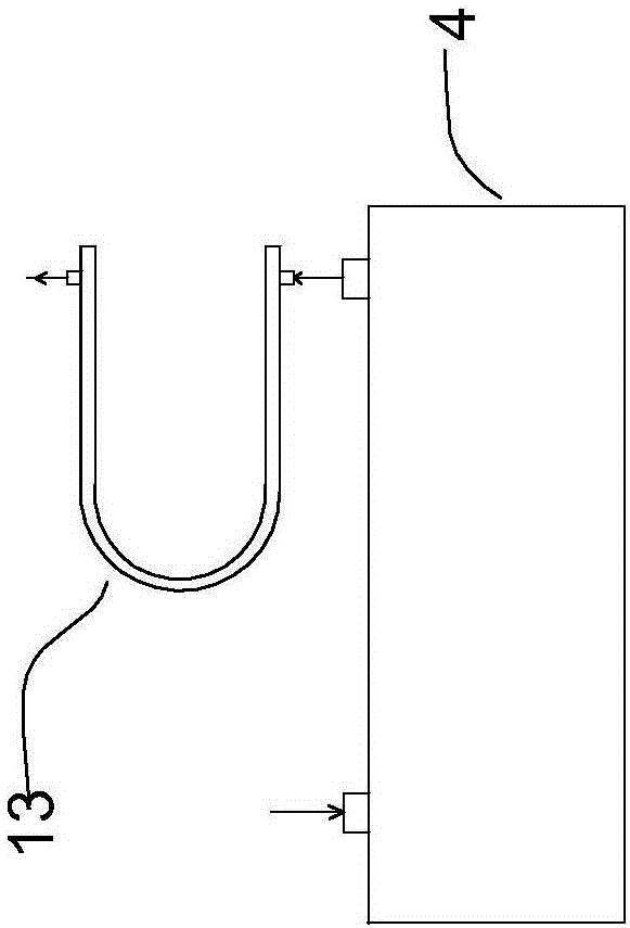
[0024] Such as Figure 1~5As shown, an energy-saving refrigeration device includes a device casing, an evaporator 1, a first cooling reducer 2, a second cooling reducer 3, a vacuum pump 4, a spray nozzle 5, a first one-way valve 6, a second Main components such as check valve 7, dryer 8 and connecting pipelines, among which the evaporator 1 is formed by connecting the vertical metal tube 1.1 and the horizontal metal tube 1.2. Usually, the vertical metal tube 1.1 is 3 arranged in parallel, and the horizontal metal tube 1.2 There are 15 pieces arranged side by side. The diameter of the vertical metal pipe 1.1 is thicker than that of the horizontal metal pipe 1.2. They can be made of stainless steel pipes or copper pipes. When connected, they are connected to form a metal disk. Metal fins are distributed on the vertical metal tube 1.1 and the ho...


PUM


Abstract

An energy-saving refrigerating device comprises an evaporator and connection pipelines. The energy-saving refrigerating device is characterized in that an outlet in the upper portion of the evaporator is connected with an inlet of a second cooling restorer firstly; then an outlet of the second cooling restorer is connected with an inlet of a vacuum pump; an outlet of the vacuum pump is connected with an inlet of a first cooling restorer; and an outlet of the first cooling restorer is connected with an injection nozzle of the evaporator. The energy-saving refrigerating device is more reasonable in structure, a vaporized refrigerant pumped out of the evaporator at the negative pressure can be sufficiently cooled and condensed, and accordingly a high energy-saving effect is achieved.

Description

technical field [0001] The invention belongs to the technical field of refrigeration, in particular to an energy-saving refrigerator using a low-temperature and low-pressure refrigerant. Background technique [0002] Traditional refrigeration equipment, such as refrigerators, freezers, cooling devices and other devices for cooling the object to be cooled, are all realized by basically the same constituent elements according to the same principle. The basic principle of an ordinary refrigeration system generally includes a compressor, a condenser, a receiving tank, an expansion valve, and an evaporator connected to each other through a refrigerant connecting pipe, and when the refrigerant charged in the system is in the system in a set direction When circulating, this refrigerant transfers heat, and this cycle of refrigerant is called a refrigeration cycle, and capillary tubes are sometimes used instead of expansion valves. In this case, for example, the capillary is a very ...

Claims


Application Information

Patent Timeline
Patent Type & Authority Applications(China)
IPC IPC(8): F25B23/00F25B39/02F25B43/00F25B49/00
CPCF25B23/00F25B39/02F25B43/00F25B49/00F25B2700/19F25B2500/18F25B2500/14F25B2500/222F25B2339/02
Inventor 冯友明
Owner 上海增融环保科技有限公司
Learn More