
Steel beam-steel pipe concrete column joint based on damage control concept

A technology of concrete-filled steel tube columns and joints, which is applied in the direction of architecture and building construction, and can solve problems such as difficult control of joint bending moment and shear force ratio, influence on joint energy consumption capacity and ductility, joint damage, etc., and achieve fast construction speed , Dissipate the input energy of the earthquake and avoid the effect of weld damage

Active Publication Date: 2017-02-15
CHONGQING UNIV
View PDF7 Cites 22 Cited by
  • Summary
  • Abstract
  • Description
  • Claims
  • Application Information

AI Technical Summary

Problems solved by technology

Under the action of reciprocating loads at the joints between CFST columns and steel beams, the welds between the flanges of steel beams and CFST columns are prone to cracking, and the flanges of steel beams are prone to out-of-plane buckling after yielding, which seriously affects the energy dissipation capacity and Ductility, it is also difficult to control the ratio of bending moment and shear force after the node enters nonlinearity in the design, which makes the damage of the node difficult to predict and control

Method used


Image

  • Steel beam-steel pipe concrete column joint based on damage control concept
  • Steel beam-steel pipe concrete column joint based on damage control concept
  • Steel beam-steel pipe concrete column joint based on damage control concept

Examples


Embodiment Construction

[0020] The present invention will be described in further detail below in conjunction with the accompanying drawings.

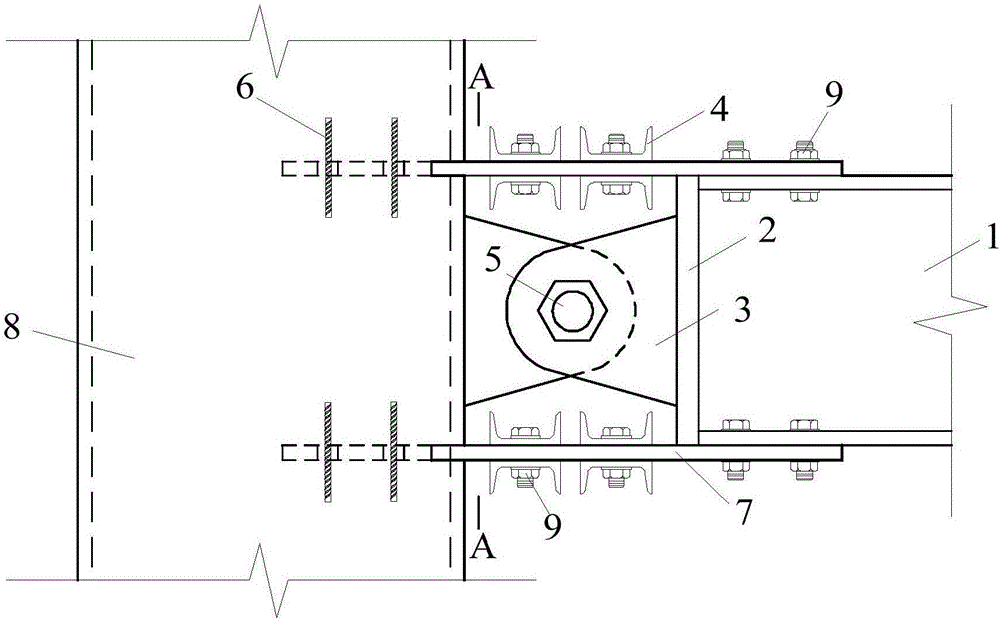
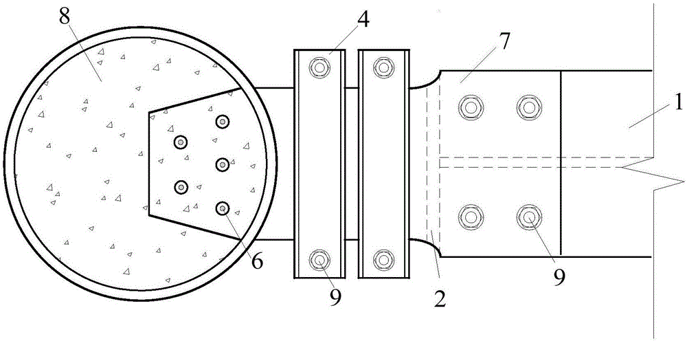
[0021] As shown in the accompanying drawings, the present invention is an energy-dissipating steel beam-concrete steel tube column joint, which consists of H-shaped steel in the steel beam, steel beam end plates, ear plates, channel steel, pins with nuts, steel bars, low It is composed of steel plate at yield point, steel pipe in steel pipe concrete column, and high-strength bolts. Its assembly procedure is as follows:

[0022] Factory prefabricated:

[0023] a. Prefabricate the basic components of the joint in the factory: H-shaped steel in the steel beam 1, steel beam end plate 2, ear plate 3, channel steel 4, pin shaft with nut 5, steel bar 6, steel plate with low yield point 7, Steel pipe 8 in steel pipe concrete column;

[0024] b. Open round holes on the upper and lower flanges of H-shaped steel 1 in the shaped steel beam, open round holes on the ste...


PUM


Abstract

The invention relates to a steel beam-steel pipe concrete column joint based on a damage control concept and belongs to the field of structural engineering. The joint comprises H-shaped steel in a shaped steel beam, a steel beam end plate, lug plates, box iron, a hinge pin with a nut, steel bars, low-yield-point steel plates, a steel pipe in a steel pipe concrete column and high-strength bolts. The steel beam end plate is welded to the H-shaped steel in the shaped steel beam. The lug plates are welded to the steel beam end plate and the steel pipe in the steel pipe concrete column. The two lug plates are connected in a hinged mode through the hinge pin with the nut and subjected to dull polish treatment. The low-yield-point steel plates are connected with the H-shaped steel through the high-strength bolts. The steel bars are inserted into holes of the low-yield-point steel plates. The low-yield-point steel plates are clamped by the box iron through the high-strength bolts. The steel beam-steel pipe concrete column joint based on the damage control concept can be applied to high-rise building combined structure systems, the shock resistance of high-rise buildings can be improved, continuous energy consumption of the joint during large strain of reciprocating loads is achieved, and the joint has broad engineering application prospects.

Description

technical field [0001] The invention relates to the field of structural engineering, in particular to the field of anti-seismic structural systems. Background technique [0002] Concrete-filled steel tube structures use concrete-filled steel tube columns as vertical load-bearing members. In recent years, they have been increasingly used in large-span and space structures, multi-storey office buildings and residences, high-rise and super high-rise buildings, and bridge structures. Due to the characteristics of high bearing capacity, good seismic performance, convenient fabrication and construction, excellent fire resistance, and good comprehensive economic benefits, CFST is widely used in frame columns in high-rise and super high-rise buildings, and is connected with steel beams to form a frame system. Under the action of reciprocating loads at the joints between CFST columns and steel beams, the welds between the flanges of steel beams and CFST columns are prone to cracking,...

Claims


Application Information

Patent Timeline
Patent Type & Authority Applications(China)
IPC IPC(8): E04B1/19E04B1/58
CPCE04B1/1903E04B2001/1957
Inventor 王宇航李硕聂鑫皮正波
Owner CHONGQING UNIV
Learn More