Pillar-to-pillar connecting joint

A technology of joints and steel columns, applied in the field of building structures, can solve the problems of large labor costs, difficult to apply column-to-column connections, and lack of fusion.

Inactive Publication Date: 2020-10-23
XI'AN UNIVERSITY OF ARCHITECTURE AND TECHNOLOGY
View PDF4 Cites 4 Cited by
  • Summary
  • Abstract
  • Description
  • Claims
  • Application Information

AI Technical Summary

Problems solved by technology

Flange connection is widely used in industrial buildings because of the problem of protruding column sections, but less in the field of construction engineering
Welding process There is always welding residual stress after welding. At the same time, due to the rapid cooling of the heat-affected zone of the welded parts, under the condition of high carbon content, it is easy to produce quenched martensite and cracks; the control is not in place during the welding process, Pores, slag inclusions, lack of fusion, lack of penetration and other defects are prone to occur
Moreover, on-site welding takes a long time and the work efficiency is low
The bolted connection often requires a large labor cost during construction, and for columns with closed sections, due to the technical problems of the bolts, it is difficult to apply bolted connections to column-to-column connections with closed sections.

Method used


Image

  • Pillar-to-pillar connecting joint
  • Pillar-to-pillar connecting joint
  • Pillar-to-pillar connecting joint

Examples


Embodiment Construction

[0018] The present invention is further described below in conjunction with accompanying drawing:

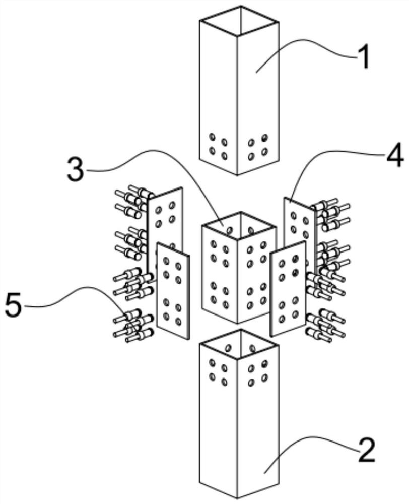
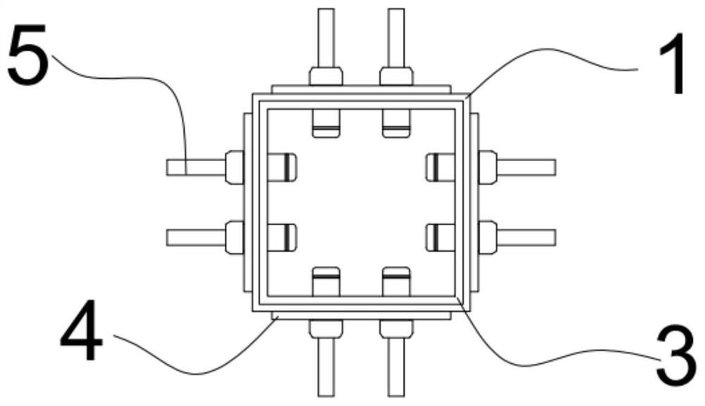
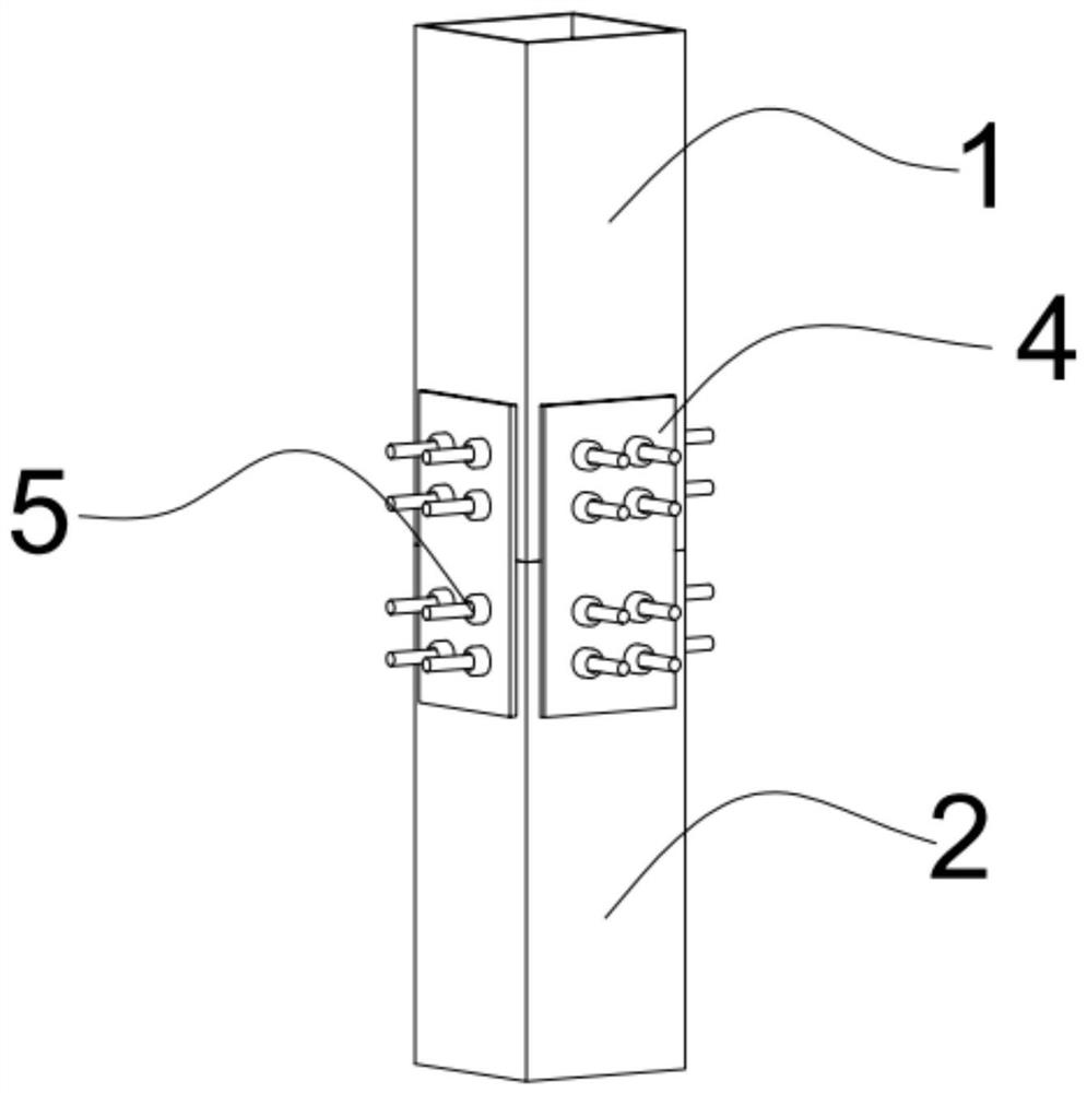
[0019] see Figure 1 to Figure 5 , a column-to-column joint, including a first steel column 1, a second steel column 2, a connecting piece 3, a ring groove rivet 5 and a connecting plate 4; the first steel column 1, the second steel column 2 and the connecting piece 3 are all It is a hollow column with the same structure. The first steel column 1 and the second steel column 2 are sleeved on both ends of the connecting piece 3 respectively. Fitting; the ends of the first steel column 1 and the second steel column 2 are in contact with each other, and several connecting plates 4 are arranged circumferentially at the contact position; the first steel column 1, the second steel column 2, the connecting plate 4 and the connection A number of bolt holes are arranged on the pieces 3, and the steel column, the connecting plate 4 and the connecting piece 3 are connected by ring groove r...


PUM


Abstract

The invention provides a pillar-to-pillar connecting joint. The connecting joint comprises a first steel pillar, a second steel pillar, a connector, ring-grooved rivets and connecting plates; the first steel pillar, the second steel pillar and the connector are in a shape of a hollow pillar and are structurally identical; the first steel pillar and the second steel pillar are respectively sleevedat two ends of the connector; the outer side walls of the connector are attached to the inner side walls of the first steel pillar and the second steel pillar; the end parts of the first steel pillarand the second steel pillar are in contact with each other, and a plurality of the connecting plates are circumferentially arranged at the contact position; a plurality of bolt holes are formed in thefirst steel pillar, the second steel pillar, the connecting plates and the connector; and the steel pillars, the connecting plates and the connector are connected together via the ring-grooved rivets. According to the connecting joint, the bolt holes are formed in the end of sealed-section steel pillars, and the steel pillars, the connecting plates and the connector are connected together via thering-grooved rivets; the joint can realize reliable connection, and the force transmission path is explicit; and the defects of cracks, air holes, slag inclusion, incomplete fusion and incomplete welding which may occur in a welding process are effectively avoided.

Description

technical field [0001] The invention relates to the technical field of building structures, in particular to a column splicing node. Background technique [0002] Most of the column connection forms are flange connection, welding and bolt connection. Flange connection is widely used in industrial buildings because of the protruding column section, but less in the field of construction engineering. Welding process There is always welding residual stress after welding. At the same time, due to the rapid cooling of the heat-affected zone of the welded parts, under the condition of high carbon content, it is easy to produce quenched martensite and cracks; the control is not in place during the welding process, Defects such as pores, slag inclusions, lack of fusion, and lack of penetration are prone to occur. Moreover, the on-site welding takes a long time and the work efficiency is low. The bolted connection often requires a large labor cost during construction, and for colum...

Claims


Application Information

Patent Timeline
Patent Type & Authority Applications(China)
IPC IPC(8): E04B1/58E04C3/32
CPCE04B1/5831E04B2001/5875E04C3/32
Inventor 郝际平安炜佳郭亮
Owner XI'AN UNIVERSITY OF ARCHITECTURE AND TECHNOLOGY
Why Eureka
Try Eureka