High-efficiency tunnel-type intermittent pyrolysis furnace

A tunnel-type furnace and tunnel-type technology are applied in the field of biomass fuel pyrolysis equipment, which can solve the problems of occupying cooling time, occupying heating time, and function failure, and achieve the effect of ensuring working pressure.

Pending Publication Date: 2017-02-15
肖国雄
View PDF10 Cites 3 Cited by
  • Summary
  • Abstract
  • Description
  • Claims
  • Application Information

AI Technical Summary

Problems solved by technology

[0003] 1. The work of the burner is unstable. With the continuous increase of pyrolysis gas, the pressure in the furnace increases accordingly, the burner cannot work normally, and the temperature of the furnace cannot rise, which affects the output
[0004] 2. Pyrolysis gas contains a lot of nitrogen, low calorific value and low utilization value
[0005] 3. During the actual operation of the designed movable guide rail, the operation steps are cumbersome, which wastes manpower and time
[0006] 4. The hydraulic ejector rod cannot withstand high temperature. In the furnace w...

Method used


Image

  • High-efficiency tunnel-type intermittent pyrolysis furnace
  • High-efficiency tunnel-type intermittent pyrolysis furnace
  • High-efficiency tunnel-type intermittent pyrolysis furnace

Examples


Embodiment Construction

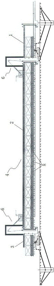
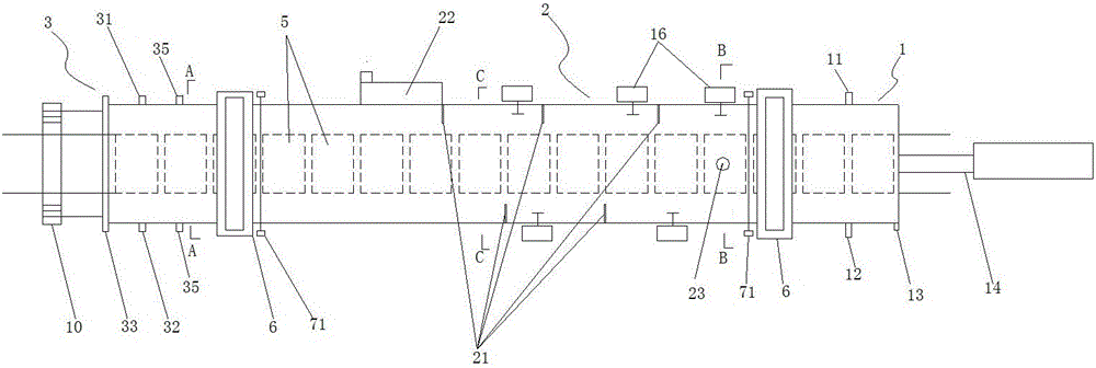
[0082] Such as Figure 1~10 As shown, a high-efficiency tunnel-type discontinuous pyrolysis furnace includes a tunnel-type furnace body 4, which is divided into a drying zone 1, a pyrolysis zone 2, and a cooling zone 3. The cross section of the furnace body 4 is rectangular or circular.

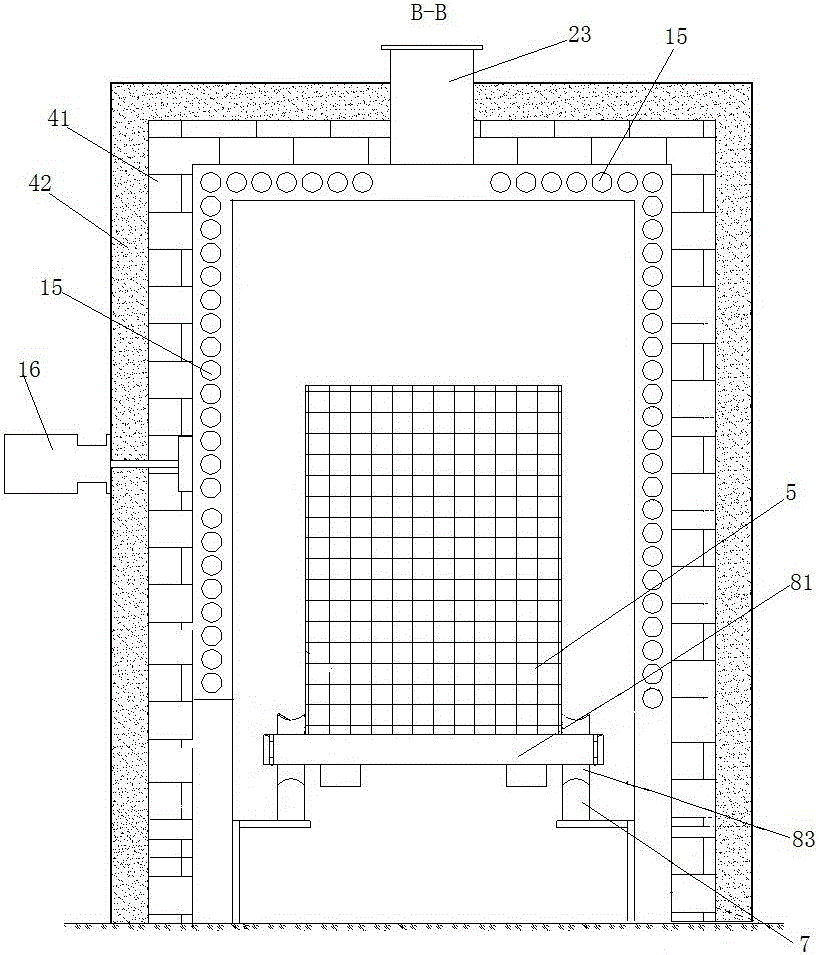
[0083] The inner bottom of the furnace body 4 is covered with a guide rail 7, and the guide rail 7 is provided with a mesh furnace frame 5 for filling the material to be heated, and at least four pairs of wheels 83 are provided at the bottom of the mesh furnace frame 5, and the wheels 83 are supported on the guide rail 7. on.

[0084] The guide rail 7 at the junction of the drying zone 1 and the pyrolysis zone 2 and the junction of the pyrolysis zone 2 and the cooling zone 3 is disconnected, and the width of the disconnection is greater than the thickness of the sealed door.

[0085] The distance between two adjacent wheels 83 of the net-shaped furnace frame 5 is greater than the width of the brea...


PUM


Abstract

The invention discloses a high-efficiency tunnel-type intermittent pyrolysis furnace. The high-efficiency tunnel-type intermittent pyrolysis furnace comprises a tunnel-type furnace body, wherein the furnace body is divided into a drying area, a pyrolysis area and a cooling area; a reticular furnace frame is arranged in the furnace body; sealing doors which can fully isolate the pyrolysis area into a closed chamber are arranged at a boundary between the drying area and the pyrolysis area and a boundary between the pyrolysis area and the cooling area; a burning chamber is connected onto the furnace body in the pyrolysis area, a smoke outlet is formed in the furnace body in the pyrolysis area, a plurality of fire tubes are arranged on the inner wall of the furnace body in the pyrolysis area and the top of the inner chamber of the furnace body, an inlet of each fire tube is communicated with the burning chamber and an outlet of each fire tube is communicated with the smoke outlet. Since the fire tubes are arranged in the furnace, pyrolysis gas is prevented from entering the furnace and influencing the working of a burner, the working pressure of the burner can be guaranteed to be normal and the furnace temperature can be guaranteed to increase and decrease according to the needs. Moreover, cumbersome steps of opening and closing movable guide rails are omitted, the manpower is saved and the operation is simpler. An ejector rod with cooling guarantees that the sealing doors can be tightly pressed without causing failure and thereby the sealing performance is guaranteed.

Description

Technical field [0001] The invention belongs to biomass fuel pyrolysis equipment, and particularly relates to a high-efficiency tunnel-type intermittent pyrolysis furnace. Background technique [0002] The first-generation tunnel-type biomass intermittent pyrolysis furnace developed by our company (patent application number 201610131973.8) is internally heated, that is, the flue gas directly contacts the biomass. Although the pyrolysis efficiency is high and the manufacturing cost is low, there are still the following defects in the actual use process: [0003] 1. The working of the burner is unstable. With the continuous increase of pyrolysis gas, the pressure in the furnace increases, the burner cannot work normally, and the furnace temperature cannot rise, which affects the output. [0004] 2. Pyrolysis gas contains more nitrogen, low calorific value, and low utilization value. [0005] 3. In the actual operation process of the designed movable rail, the operation steps are cumber...

Claims


Application Information

Patent Timeline
IPC IPC(8): C10B53/02C10B47/02C10B47/46C10B45/00
CPCC10B45/00C10B47/02C10B47/46C10B53/02Y02E50/10
Inventor 肖国雄
Owner 肖国雄
Why Eureka
Try Eureka