
Feeding and discharging equipment for water-immersed ultrasonic flaw detection equipment for direct-axis component

A component and ultrasonic technology, applied in the field of loading and unloading equipment, can solve the problems of high efficiency, low work efficiency, and complicated device structure of the water immersion automatic flaw detection machine, and achieve improved automation of loading, low cost, and The effect of compact and simple equipment structure

Active Publication Date: 2017-02-15
ZHUZHOU TIANLI FORGING IND
View PDF5 Cites 9 Cited by
  • Summary
  • Abstract
  • Description
  • Claims
  • Application Information

AI Technical Summary

Problems solved by technology

This kind of feeding method wastes time, the efficiency is extremely low, and the high efficiency of the water immersion automatic flaw detection machine cannot be brought into play.
However, Chinese patent CN200910089090.5 discloses a device for inspecting rail transit axles and other straight shaft parts using ultrasonic flaw detection technology. Discharging table, manipulator traverse support, traverse manipulator, flaw detection mechanism and label spraying mechanism, among them, the feeding workbench ensures that the axle under test can roll slowly to the normal mechanism, and the blocking and unloading machine prevents multi-axis from entering the normal mechanism. The positive mechanism normalizes the axle under test entering the calibration table, the traverse manipulator on the manipulator traverse bracket grabs the axle under test to the water tank, and the traverse manipulator grabs the axle under test after scanning to the discharge under test Axle, the structure of the device is complicated and the working efficiency is not high

Method used


Image

  • Feeding and discharging equipment for water-immersed ultrasonic flaw detection equipment for direct-axis component
  • Feeding and discharging equipment for water-immersed ultrasonic flaw detection equipment for direct-axis component
  • Feeding and discharging equipment for water-immersed ultrasonic flaw detection equipment for direct-axis component

Examples


Embodiment Construction

[0022] Embodiments of the present invention are described in detail below, examples of which are shown in the drawings, wherein the same or similar reference numerals designate the same or similar elements or elements having the same or similar functions throughout. The embodiments described below by referring to the figures are exemplary only for explaining the present invention and should not be construed as limiting the present invention.

[0023] In describing the present invention, it is to be understood that the terms "upper", "lower", "front", "rear", "top", "bottom", "inner", "outer" etc. indicate an orientation or position The relationship is based on the orientation or positional relationship shown in the drawings, and is only for the convenience of describing the present invention and simplifying the description, rather than indicating or implying that the referred device or element must have a specific orientation, be constructed and operated in a specific orientati...


PUM

PropertyMeasurementUnit
lengthaaaaaaaaaa

Abstract

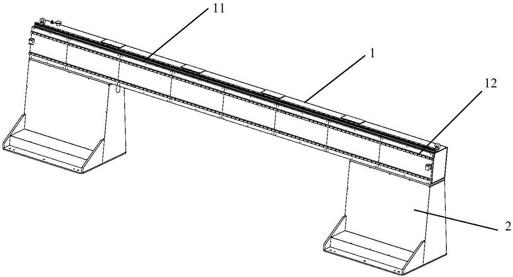
The invention provides feeding and discharging equipment for water-immersed ultrasonic flaw detection equipment for a direct-axis component. The feeding and discharging equipment for the water-immersed ultrasonic flaw detection equipment for the direct-axis component comprises a feeding device, a moving device and a discharging device. In the embodiment, the direct-axis component is born through the feeding device; the direct-axis component is grabbed and fed into the flaw detection equipment through a manipulator of the moving device; after the direct-axis component is detected, the direct-axis component is fed into the discharging device through the moving device. The feeding and discharging equipment for the water-immersed ultrasonic flaw detection equipment for the direct-axis component has the beneficial effects that the direct-axis component can be fed into a flaw detection machine and discharged from the flaw detection machine, so that the using frequency of an overhead travelling crane is reduced, and the labour efficiency is improved.

Description

technical field [0001] The invention relates to the technical field of flaw detection of straight shaft parts, in particular to a loading and unloading device for water immersion ultrasonic flaw detection equipment for straight shaft parts. Background technique [0002] Straight shaft parts generally require ultrasonic flaw detection inside. Such parts are generally long in length and heavy in weight. For example, the axle of an important force-bearing part on a railway vehicle usually has a heavy weight, generally more than 1 ton. There are generally two types of ultrasonic flaw detection methods commonly used at present: manual contact ultrasonic flaw detection and automatic non-contact flaw detection. These two flaw detection methods have their own advantages and disadvantages. The manual contact ultrasonic flaw detection method requires the flaw detector to carry out contact flaw detection with the probe of the flaw detector and the workpiece. The labor intensity is high...

Claims


Application Information

Patent Timeline
Patent Type & Authority Applications(China)
IPC IPC(8): B65G11/02B65G11/20B65G47/88B65G47/90G01N29/04
CPCB65G11/023B65G11/203B65G47/8823B65G47/901B65G2201/0217G01N29/04
Inventor 熊勇军阮培亮牛迎春段怡雄阳冬鸿李平川陈江
Owner ZHUZHOU TIANLI FORGING IND
Learn More