Eureka AIR delivers breakthrough ideas for toughest innovation challenges, trusted by R&D personnel around the world.

Working method of magnetic core test line body

A working method and magnetic core technology, applied in the direction of manufacturing tools, metal processing equipment, auxiliary devices, etc., can solve the problems of easy misoperation, high production cost, manual operation, etc., and achieve the effect of improving stability and saving the number of operators

Active Publication Date: 2017-02-15
DALIAN YUN MING AUTOMATION TECH
View PDF5 Cites 5 Cited by
  • Summary
  • Abstract
  • Description
  • Claims
  • Application Information

AI Technical Summary

Problems solved by technology

[0002] Magnetic cores are widely used in a wide range of fields. At present, the assembly of magnetic cores in the market is mainly done manually. Through manual assembly by a large number of workers, not only the production cost is high, but also the assembly efficiency is low, which cannot meet the industrialization needs of modern society.
Relying on manual work will result in situations and difficulties such as manual work, difficult work, visual fatigue and easy misoperation.

Method used


Image

  • Working method of magnetic core test line body
  • Working method of magnetic core test line body
  • Working method of magnetic core test line body

Examples


Embodiment 1

[0024] This embodiment provides a working method for a magnetic core test wire body, and the specific steps are as follows:

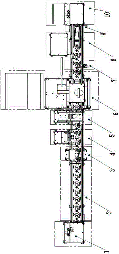
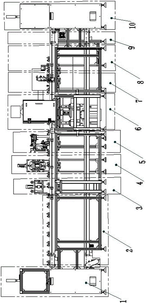
[0025] S1, put the magnetic core into the jig at operator station 2;

[0026] S2, the transmission device transmits the jig to the press-in station 3, the blocking device blocks it, holds the positioning device to lift the jig, and starts to press it in. After pressing in, hold the positioning device to drop it and put it into the transmission device;

[0027] S3, the transfer device transfers the jig to the cleaning station 4, the blocking device and the holding and positioning device act as above, the cleaning device starts to clean, and after the cleaning is completed, the holding and positioning device drops it and puts it into the transfer device;

[0028] S4, the transfer device transfers the jig to the flipping station 5, the blocking device and the holding positioning device act as above, the manipulator flips the magnetic core by 90 degrees an...

Embodiment 2

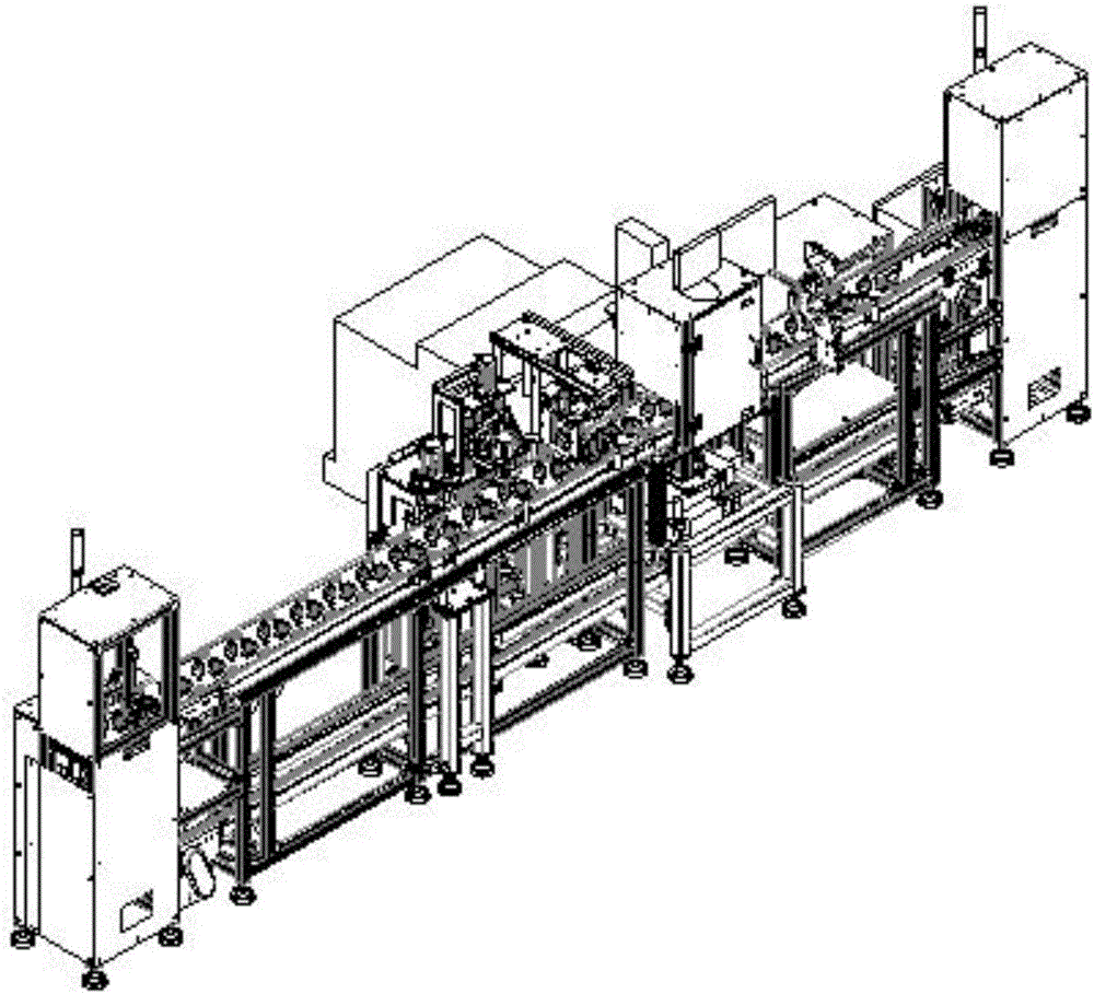
[0035] This embodiment provides a magnetic core test wire body as described in Embodiment 1, including: sequentially connected lifting device I1, operator station 2, press-in station 3, cleaning station 4, turning station 5, Welding station 6, on-off detection station 7, code scanning station 8, manual blanking station 9, lifting device II 10; the operator station 2, pressing station 3, cleaning station 4, turning station Station 5, welding station 6, on-off detection station 7, code scanning station 8, and manual blanking station 9 are all provided with blocking devices and holding positioning devices; the lifting device I1 is connected with operator station 2 Between operator station 2 and press-in station 3, press-in station 3 and cleaning station 4, cleaning station 4 and turning station 5, turning station 5 and welding station Between 6, between welding station 6 and on-off detection station 7, between on-off detection station 7 and code scanning station 8, between code s...


PUM


Abstract

The invention discloses a working method of a magnetic core test line body. The working method comprises the following specific steps: a magnetic core is placed in a jig at an operation station; and a transmission device conveys the jig to a press-in station, presses in the jig and conveys the jig to a sweeping station, a sweeping device starts to sweep, after the sweeping is concluded, the transmission device conveys the jig to a turnover station, a manipulator turns over the magnetic core a certain angle and then places the magnetic core, the transmission device conveys the jig to a welding station, after the welding is concluded, the transmission device conveys the jig to an on-off detection station, the on-off detection station starts to work and judges good products and defective products, after the detection is completed, the transmission device conveys the jig to a code scanning station, after code scanning is completed, the transmission device conveys the jig to a manual unloading station, and the magnetic core is manually taken away. The working method disclosed by the invention is capable of automatically pressing in, sweeping, turning over, welding and judging the good products and defective products, and improving the stability and high efficiency of working performance.

Description

technical field [0001] The invention relates to the technical field of magnetic core assembly equipment testing, in particular to a working method for a magnetic core testing line. Background technique [0002] Magnetic cores are widely used in a wide range of fields. At present, the assembly of magnetic cores in the market is mainly done manually. Through manual assembly by a large number of workers, not only the production cost is high, but also the assembly efficiency is low, which cannot meet the industrialization needs of modern society. Relying on manual work will lead to situations and difficulties such as manual work, difficult work, visual fatigue and easy misoperation. Contents of the invention [0003] In view of the above-mentioned defects existing in the prior art, the present application provides a working method of the magnetic core test wire body, which can automatically press in, automatically clean, automatically turn over, automatically weld, and automat...

Claims


Application Information

Patent Timeline
IPC IPC(8): B23K37/047B23K37/00
CPCB23K37/00B23K37/047
Inventor 王承刚田志涛丁力
Owner DALIAN YUN MING AUTOMATION TECH
Why Eureka
Eureka Blog
Learn More