
Sectional step type cooling device for hot rolling of high-strength steel bars

A high-strength steel bar and cooling device technology, applied in the direction of workpiece cooling devices, metal rolling, metal rolling, etc., can solve the problems of inflexible cooling paths, limited cooling speed of the core, poor corrosion resistance, etc., and achieve reduction The effect of fresh water consumption, increased strength, reduced alloy content and

Active Publication Date: 2017-02-15
CENT IRON & STEEL RES INST
View PDF8 Cites 8 Cited by
  • Summary
  • Abstract
  • Description
  • Claims
  • Application Information

AI Technical Summary

Problems solved by technology

Due to the water seal in the water pipe, the shortest length of the cooling section is limited, resulting in an inflexible cooling path, which can only be cooled to the bottom, and the surface temperature is easily lower than the martensitic point, and the surface is affected by the film boiling of water. Speed ​​limited
In addition, although the amount of alloy added by the water-piercing process is greatly reduced, there are problems of martensite ring welding softening after water-piercing and red rust on the surface after water-piercing. The corrosion resistance is poor, which seriously affects subsequent use. Users Even put forward the request of return or price reduction, especially the steel bars exported abroad have stricter requirements on surface quality

Method used


Image

  • Sectional step type cooling device for hot rolling of high-strength steel bars
  • Sectional step type cooling device for hot rolling of high-strength steel bars
  • Sectional step type cooling device for hot rolling of high-strength steel bars

Examples


Embodiment Construction

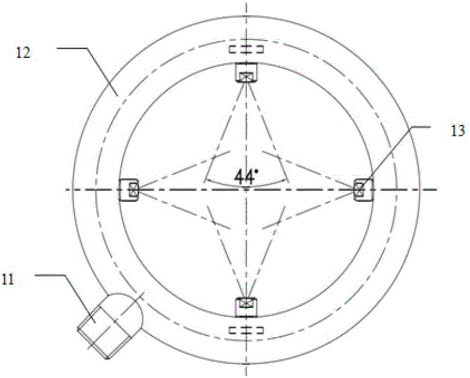
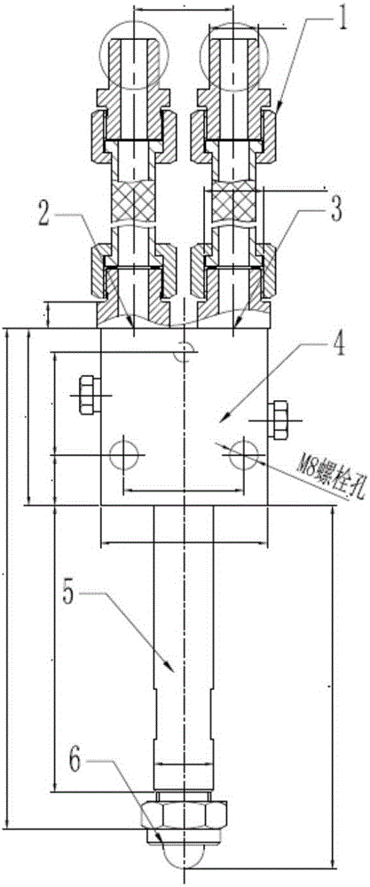
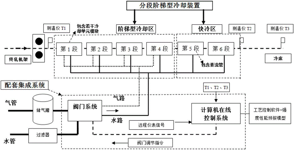
[0023] In order to illustrate the specific implementation of the step-by-step cooling device for a hot-rolled high-strength steel bar of the present invention, the following will be combined with the attached figure 1 -7, its basic principles, technical characteristics, actual operation and adjustment methods are explained as follows.

[0024] Such as figure 1 As shown, the stepwise cooling device for hot-rolled high-strength steel bars of the present invention is mainly composed of a stepwise cooling zone and a fast cooling zone. Among them, the step-by-step cooling zone is composed of 15 groups of water mist vaporization cooling nozzles and water mist strengthening nozzles in 4 sections, which is a cooling-returning step cooling section, and the water mist vaporization cooling nozzles and water mist strengthening nozzles are distributed at intervals; the fast cooling zone It consists of two sections of fast cooling turbulent tube coolers; the steel bars pass through the sta...


PUM


Abstract

The invention provides a sectional step type cooling device for hot rolling of high-strength steel bars, and belongs to the field of steel rolling equipment. The sectional step type cooling device comprises two cooling areas, namely a sectional step type cooling area and a rapid cooling area. The sectional step type cooling device further comprises a mating integrated system which is connected with the sectional step type cooling device. The sectional step type cooling area is composed of four cooling-warming step type cooling sections which are composed of 10-25 sets of mist evaporative-cooling nozzles and mist reinforcing nozzles, the mist evaporative-cooling nozzles and the mist reinforcing nozzles are distributed in a spaced mode, and the distance between the mist evaporative-cooling nozzles and the mist reinforcing nozzles is controlled to be 20-240 mm and can be adjusted according to the rolling speed and the rolling temperature. The rapid cooling area is composed of one to two sections of rapid-cooling turbulent flow pipe coolers. The steel bars sequentially penetrate through the sectional step type cooling area and the rapid cooling area, and all technological parameters are adjusted and controlled through the mating integrated system. The sectional step type cooling device for hot rolling of the high-strength steel bars has the advantage that the purposes of improving the morphology, structure and completeness of surface oxidized scale, and delaying rusting and improving the micro-structure in the sale cycle are achieved.

Description

technical field [0001] The invention belongs to the technical field of steel rolling equipment, and in particular provides a step-by-step cooling device for hot-rolling high-strength steel bars. This water mist vaporization cooling device makes full use of the advantages of water mist vaporization cooling and water penetration cooling technology, and uses the phase change latent heat of vaporization of water Δhv=540cal / g and the specific heat of water Cp=1cal / g℃ in different cooling sections. The basic principle, using the step-by-step accelerated cooling method, provides an effective phase transformation strengthening and controlled cooling device for hot-rolled high-strength steel bars. Background technique [0002] At present, the post-rolling cooling equipment for hot-rolled ribbed steel bars at home and abroad is mainly water-piercing pipes, all of which adopt and learn from the Tempcore water-piercing cooling technology developed by the Belgian Metallurgical Research I...

Claims


Application Information

Patent Timeline
IPC IPC(8): B21B45/02
CPCB21B45/0209B21B2045/0212B21B2201/06
Inventor 王卫卫张江玲肖金福白宇翟静芳侯中晓赵舸罗啟泷
Owner CENT IRON & STEEL RES INST
Learn More