Eureka AIR delivers breakthrough ideas for toughest innovation challenges, trusted by R&D personnel around the world.

A Symmetric Broadband Planar Endfire Circularly Polarized Antenna

A circularly polarized antenna, end-fire technology, applied in antennas, resonant antennas, electrical short antennas, etc., can solve the problem of insufficient bandwidth of end-fire circularly polarized antennas, improve antenna impedance matching, solve insufficient bandwidth, and improve the average gain effect

Inactive Publication Date: 2019-05-17
SHANXI UNIV
View PDF1 Cites 0 Cited by
  • Summary
  • Abstract
  • Description
  • Claims
  • Application Information

AI Technical Summary

Problems solved by technology

[0004] In order to solve the problem of insufficient bandwidth of existing end-fire circularly polarized antennas, the present invention provides a symmetrical broadband planar end-fire circularly polarized antenna

Method used


Image

  • A Symmetric Broadband Planar Endfire Circularly Polarized Antenna
  • A Symmetric Broadband Planar Endfire Circularly Polarized Antenna
  • A Symmetric Broadband Planar Endfire Circularly Polarized Antenna

Examples


Embodiment Construction

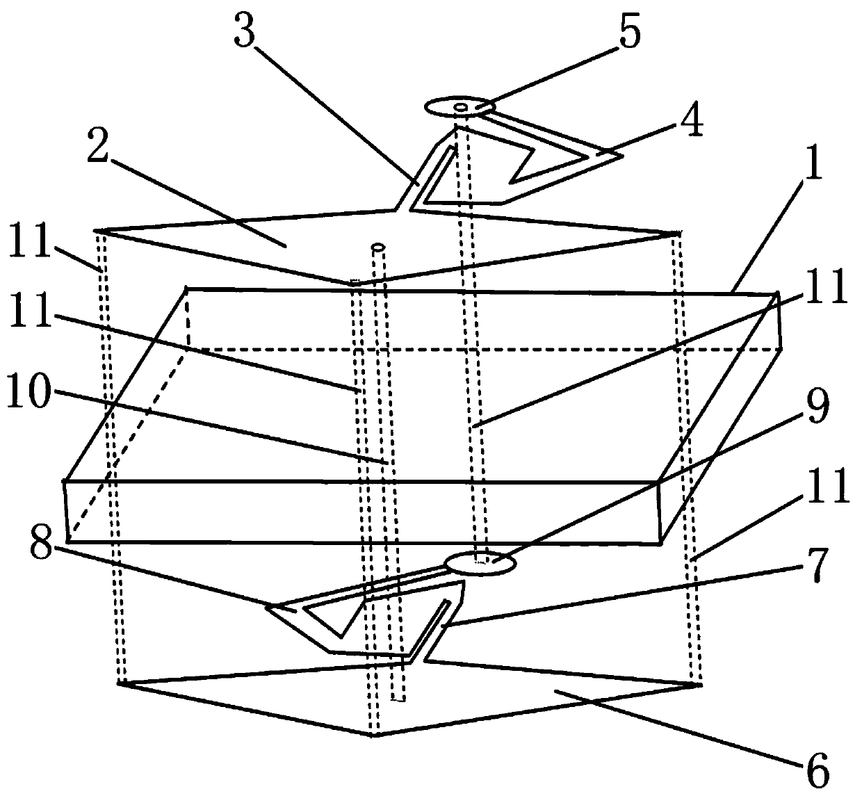
[0027] A symmetrical broadband planar end-fire circularly polarized antenna, including a dielectric substrate 1, an upper metal patch, and a lower metal patch;

[0028] The upper metal patch and the lower metal patch are respectively mounted on the upper surface and the lower surface of the dielectric substrate 1;

[0029] The upper metal patch includes an upper diamond-shaped metal patch 2, an upper coupling transmission line 3, an upper arm-shaped magnetic dipole 4, and an upper end shot circle 5;

[0030] The lower-layer metal patch includes a lower-layer diamond-shaped metal patch 6, a lower-layer coupling transmission line 7, a lower-layer arm-shaped magnetic dipole 8, and a lower-layer end shot circle 9;

[0031] Among them, the upper diamond-shaped metal patch 2 and the lower diamond-shaped metal patch 6 are directly opposite to each other; a coaxial feed point 10 is provided between the center of the upper diamond-shaped metal patch 2 and the center of the lower diamond-shaped ...


PUM


Abstract

The invention relates to an end emitting circularly polarized antenna and particularly relates to a symmetrical broadband plane end emitting circularly polarized antenna. The problem of the insufficient bandwidth of an existing end emitting circularly polarized antenna is solved. The symmetrical broadband plane end emitting circularly polarized antenna comprises a dielectric substrate, an upper layer metal patch, and a lower layer metal patch. The upper layer metal patch comprises an upper layer diamond-shaped metal patch, an upper layer coupling transmission wire, an upper layer arm-shaped magnetic dipole, and an upper layer end emitting circle. The lower layer metal patch comprises a lower layer diamond-shaped metal patch, a lower layer coupling transmission wire, a lower layer arm-shaped magnetic dipole, and a lower layer end emitting circle. The diamond-shaped metal patches, the coupling transmission wires and the end emitting circles of the upper layer and the lower layer are opposite. The arm-shaped magnetic dipoles of the upper layer and the lower layer are symmetrical on an X axis. At the same time, the three corner parts of the upper and lower layer diamond-shaped metal patches are provided with three short circuit metal through holes. A short circuit metal through hole is arranged between the center of the upper layer end emitting circle and the center of the lower layer end emitting circle. The symmetrical broadband plane end emitting circularly polarized antenna is suitable for wireless communication.

Description

Technical field [0001] The invention relates to an end-fire circularly polarized antenna, in particular to a symmetrical broadband planar end-fire circularly polarized antenna. Background technique [0002] With the development of communication technology, circularly polarized antennas have been widely used in radar, electronic countermeasures, satellite communications and other fields due to their advantages in suppressing rain and fog and anti-multipath reflection. The principle of implementing a circularly polarized antenna is to generate two spatially orthogonal linearly polarized components with equal amplitude and a phase difference of 90 degrees. At present, there are mainly four types of ways to realize circular polarization: the first one, the single-feed method realizes circular polarization; the second one, the multi-feed method realizes circular polarization; the third, the multiple method realizes circular polarization; The fourth type is the traveling wave method t...

Claims


Application Information

Patent Timeline
Patent Type & Authority Patents(China)
IPC IPC(8): H01Q1/38H01Q9/04
CPCH01Q1/38H01Q9/0492
Inventor 张文梅莫文东韩丽萍马润波刘宇峰
Owner SHANXI UNIV
Why Eureka
Eureka Blog
Learn More