


Quick Research
Generate reliable direction feasibility study reports for your R&D in just a few steps.

Technical Q&A
Discover and master advanced knowledge NOW. Basics, ideas, possibilities, all at once.

Find Solutions
As an expert in R&D theories, this can generate solutions to your technical problems instantly.

Evaluate Feasibility
Analyze your overall solution with one click, know your potential R&D risks in advance.

Monitor Landscape
Get weekly tech updates, stay abreast of the latest tech innovations and key insights.
Method and device for performing underground periodic huff-puff oil extraction by utilizing supercritical carbon dioxide
A carbon dioxide and supercritical technology, which is applied in the fields of mining fluid, earthwork drilling, wellbore/well components, etc., can solve the problems of insufficient carbon dioxide recovery and increased greenhouse gas volume, so as to achieve less environmental pollution, avoid waste of resources, Reduce the effect of the greenhouse effect
- Summary
- Abstract
- Description
- Claims
- Application Information
AI Technical Summary
Problems solved by technology
Method used
Image

Examples
Embodiment 1
[0051] Embodiment 1 Taking the R53 block of JL Oilfield as the research object, a geological structure model, a sedimentary facies model and an attribute model under facies control are established for multiple wells in the block, and at the same time, the numerical simulation of production and water cut is completed on the basis of the geological model. For the fitting work, taking Well R53-3 in this block as an example, the oil production cycle huff and puff of this well was simulated to verify the feasibility of this method.
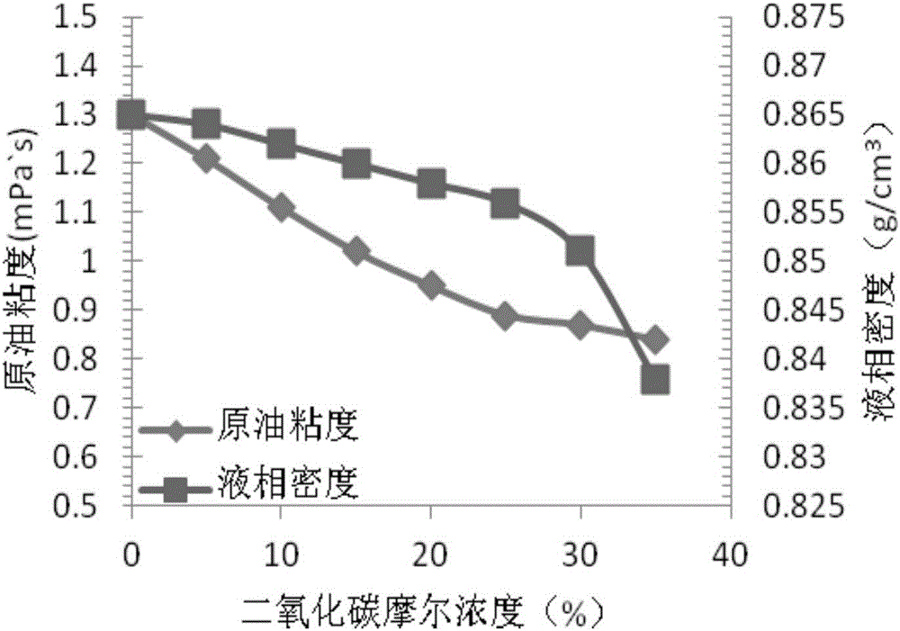
[0052] Well R53-3 is a horizontal well, where the interlayer interference is small, the oil layer is well sealed, and the gas injection trap can be formed. At the same time, the permeability of this area is low, and the pressure and temperature of the oil layer are high, which meets the requirement of supercritical injection. carbon dioxide conditions.
[0053] According to this embodiment, the method for downhole periodical huff and puff recovery usin...
Embodiment 2
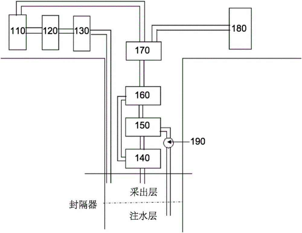
[0076] like figure 2 As shown, Embodiment 2 proposes a device for downhole periodic huff and puff oil recovery using supercritical carbon dioxide.
[0077] According to Embodiment 2, the device for downhole periodic huff and puff oil recovery utilizing supercritical carbon dioxide comprises: a carbon dioxide storage tank 110, a heater 120, a booster pump 130, a gas-liquid separator 140, an oil-water separator 150, an oil-gas mixing pump 160, an oil-gas Separator 170, oil storage tank 180.
[0078] The carbon dioxide storage tank 110, the heater 120, the booster pump 130 and the oil storage tank 180 are all arranged outside the well, and the gas-liquid separator 140, the oil-water separator 150, the oil-gas The mixing pump 160 and the oil-gas separator 170 are both arranged in the well; the carbon dioxide storage tank 110 is connected to the heater 120, and the heater 120 is connected to one end of the booster pump 130, and the booster pump The other end of 130 goes deep int...
PUM
 Abstract
Description
Claims
Application Information
 - R&D Engineer
- R&D Manager
- IP Professional
- Industry Leading Data Capabilities
- Powerful AI technology
- Patent DNA Extraction
Browse by: Latest US Patents, China's latest patents, Technical Efficacy Thesaurus, Application Domain, Technology Topic, Popular Technical Reports.
© 2024 PatSnap. All rights reserved.Legal|Privacy policy|Modern Slavery Act Transparency Statement|Sitemap|About US| Contact US: help@patsnap.com