
Radar device

A radar and buffer sleeve technology, applied in the field of reversing radar, can solve problems such as tailing and large holes, and achieve the effect of improving accuracy

Active Publication Date: 2017-02-01
HEFEI SOFTEC AUTO ELECTRONICS
View PDF6 Cites 2 Cited by
  • Summary
  • Abstract
  • Description
  • Claims
  • Application Information

AI Technical Summary

Problems solved by technology

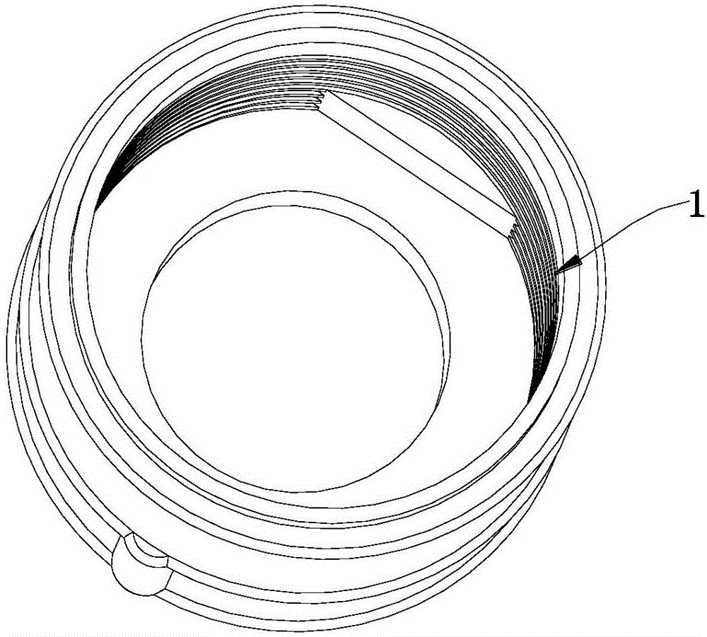
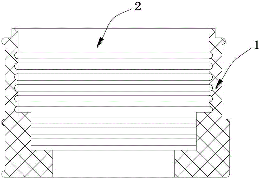
[0003] However, there are still obvious defects in the existing buffer sleeves: from figure 1 It can be seen that there is a relatively large cavity at the rear end of the existing buffer sleeve 1
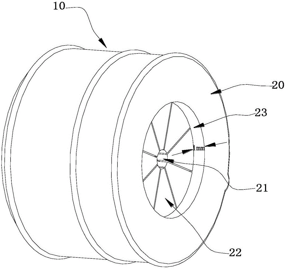
Therefore, the ultrasonic waves emitted by the sensor will oscillate back and forth through the cavity at the rear end of the buffer sleeve, resulting in adverse phenomena such as bifurcation, jitter, and tailing in the aftermath of the radar probe.

Method used


Image

  • Radar device
  • Radar device
  • Radar device

Examples


Embodiment Construction

[0013] Combine below Figure 3 to Figure 6 , the present invention is described in further detail.

[0014] like Figure 3-6 As shown, the present embodiment provides a kind of radar, and this radar comprises housing and sensor, and buffer sleeve 10 is arranged between housing, sensor, and the rear end of buffer sleeve 10 has end cover 20, and the middle part of end cover 20 is provided with for detection. The aperture 21 that core wire passes through. By adding an end cap 20 at the rear end of the buffer sleeve 10, the end cap 20 there is an integrally formed silicone rubber end cap, which closes the cavity at the rear end of the buffer sleeve, leaving only a small hole for the sensor core wire to pass through. twenty one. When assembling, first pass the probe wire of the sensor 30 through the small hole 21 on the end cover 20 of the buffer sleeve 10, and insert the sensor 30 into the buffer sleeve 10 until the end surface of the probe wire of the sensor 30 is connected wi...


PUM


Abstract

The invention discloses a reversal radar device utilized by a vehicle and belongs to the radar measurement technology field. The radar device comprises a casing and a sensor, wherein a buffering sleeve is arranged between the casing and the sensor, a back end of the buffering sleeve is integrated with a silicone rubber end cap, and a middle portion of the end cap is provided with a hole for penetration of a probe core. Through the radar device, the back end of the buffering sleeve is provided with the end cap, so the back end of the buffering sleeve has no cavity but only the hole for penetration of the probe core, supersonic waves emitted by the sensor are absorbed through a tail portion of the buffering sleeve, bifurcation, jittering and trailing phenomena generated in a user process of the reversal radar device are avoided, and use accuracy of the radar device is improved.

Description

technical field [0001] The invention relates to the technical field of radar measurement, in particular to a parking radar for vehicles. Background technique [0002] At present, the reversing radar is generally used to measure the distance from the obstacle to the vehicle to ensure the safety of the vehicle. Install the reversing radar on the bumper of the vehicle when in use, and the ultrasonic sensor is a vibrating component. When the ultrasonic sensor vibrates and contacts a hard object (such as the sensor housing), the vibration will be transmitted to the object, making the sensor housing Vibrating with a hard object, when the vibration frequency of the sensor shell is the same as that of the ultrasonic sensor, a resonance phenomenon will occur. In this way, the reverberation of the sensor will be affected, and the aftermath of the radar probe will become larger or bifurcate, resulting in misjudgment of surrounding obstacles. Therefore, technicians absorb the vibratio...

Claims


Application Information

Patent Timeline
IPC IPC(8): G01S15/93
CPCG01S15/931
Inventor 许永华梅炜炜陈静汪涛沈家栋
Owner HEFEI SOFTEC AUTO ELECTRONICS
Learn More