A household escape device

An escape device and home-use technology, applied in the field of escape devices, can solve the problems of poor controllability, single function, unusability, etc., and achieve the effect of high safety in use, strong controllability and reasonable design

Inactive Publication Date: 2018-09-14
SHANDONG JIAOTONG UNIV
View PDF5 Cites 0 Cited by
  • Summary
  • Abstract
  • Description
  • Claims
  • Application Information

AI Technical Summary

Problems solved by technology

[0002] There are more and more high-rise buildings in cities in modern society. When a fire or other emergency occurs in the building, people usually flock to the elevator, but this wrong approach will increase the risk of danger during the escape process.
If people do not borrow tools and escape directly from the stairs, they are usually prone to danger due to impact due to the lack of protection from external devices.
When people cannot escape for a long time, they need to use firefighters and firefighting equipment to escape, but there are many potential dangers in the process of waiting for the arrival of outside firefighters.
In order to increase the chance of voluntary escape, people usually place escape tools at home at present, but the existing escape equipment usually has a single function, or can only escape from the stairs, or can only escape from the window, if people only prepare one escape tool , and when the application channel of this escape tool is not smooth, it will cause people to be unable to use this escape tool to escape; if the escape tool of multiple escape methods is prepared, the cost will increase and the space in the room will be additionally occupied; in addition, the current Some escape tools have poor controllability during the escape process, cannot accurately and reliably control the running speed, and have low safety. Obviously, the existing escape tools cannot meet people's needs more effectively

Method used


Image

  • A household escape device
  • A household escape device
  • A household escape device

Examples


Embodiment Construction

[0023] In order to clearly illustrate the technical features of this solution, the present invention will be described in detail below through specific implementation modes and in conjunction with the accompanying drawings.

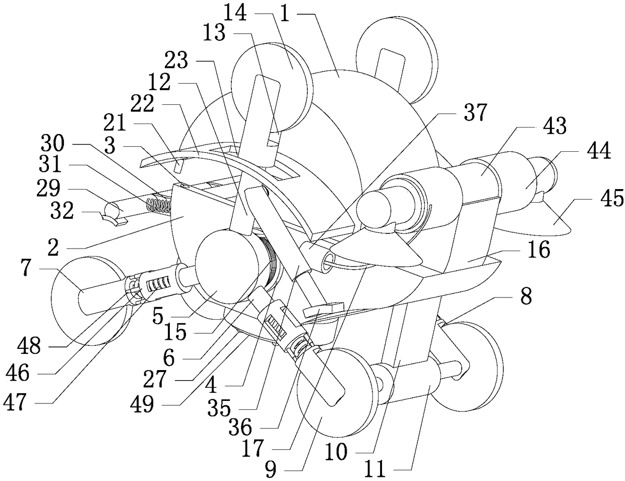
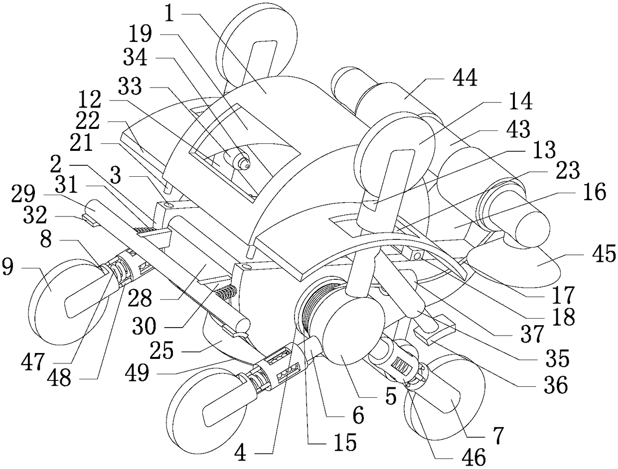
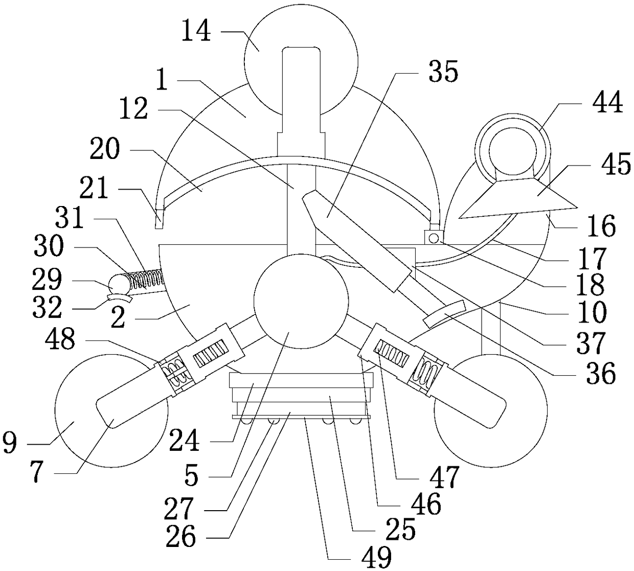
[0024] Such as Figure 1-9As shown in , a household escape device includes an escape cabin composed of an upper casing 1 and a lower casing 2, a rotating device is provided at the bottom of the lower casing 2, and a plug-in device is symmetrically arranged on the left top of the lower casing 2. Mounting hole 3, on the left side of the lower case 2 is provided with a lower case 2 through groove connecting the inside and outside of the lower case 2, and a front brake device is movably connected in the lower case 2 through groove through a rotating shaft. A horizontally arranged fixed shaft 4 is symmetrically fixed on the front and rear side walls respectively, and a vertically arranged supporting circular plate 5 is respectively fixed on the outer end faces...


PUM


Abstract

The invention relates to the field of escape devices, in particular to a domestic escape device. The domestic escape device comprises an escape compartment; a rotating device is arranged at the bottom of the escape compartment; plug-in mounting holes are symmetrically formed in the top on the left side of a lower housing; a lower housing through groove for communicating the inside of the lower housing with the outside of the lower housing is formed in the left side of the lower housing; a front brake device is movably connected to the lower housing through groove through a rotating shaft; the lower end of the front brake device is fixedly connected with a buffer device; a rear brake device is arranged on the rear side of the escape compartment; a support positioning device is arranged under the escape compartment; and both sides of the escape compartment are respectively and fixedly connected with a slow descending device. The domestic escape device disclosed by the invention is simple in structure, reasonable in design and easy to operate; people can escape from a stair or from a window, so that the generality is high; and the controllability of the escape tool in an escape process is high, errors in the operation process can be reduced effectively, the use security is high, the needs of people can be met effectively, and problems existing in the prior art are solved.

Description

Technical field: [0001] The invention relates to the field of escape devices, in particular to a household escape device. Background technique: [0002] There are more and more high-rise buildings in cities in modern society. When a fire or other emergencies break out in the building, people usually flock to the elevator, but this wrong approach will increase the probability of danger during the escape process. If people do not borrow tools and directly escape from the stairs, because of lacking the protection of external devices, they are usually prone to danger due to impact. When people cannot escape for a long time, they need to use firefighters and firefighting equipment to escape, but there are many potential dangers in the process of waiting for the arrival of outside firefighters. In order to increase the chance of voluntary escape, people usually place escape tools at home at present, but the existing escape equipment usually has a single function, or can only esca...

Claims


Application Information

Patent Timeline
Patent Type & Authority Patents(China)
IPC IPC(8): B62D57/024
CPCB62D57/024
Inventor 钱川周辰孙龙杰
Owner SHANDONG JIAOTONG UNIV
Why Eureka
Try Eureka