
Control circuit of remote controller with backlight screen

A technology for controlling circuits and remote controls, which is applied in the field of remote controls to achieve the effects of prolonging battery life and stabilizing boosted output voltage values

Active Publication Date: 2017-01-25
北京意同创科技有限公司
View PDF37 Cites 3 Cited by
  • Summary
  • Abstract
  • Description
  • Claims
  • Application Information

AI Technical Summary

Problems solved by technology

[0003] In order to overcome the deficiencies of the prior art, the object of the present invention is to provide a remote controller control circuit with a backlight screen, which uses a boost circuit without an integrated chip instead of a DC / DC boost power supply chip to achieve the same boost effect , and solve the problem of automatic reset of the remote control, and the battery life is relatively longer

Method used


Image

  • Control circuit of remote controller with backlight screen
  • Control circuit of remote controller with backlight screen
  • Control circuit of remote controller with backlight screen

Examples


Embodiment Construction

[0017] Below, in conjunction with accompanying drawing and specific embodiment, the present invention is described further:

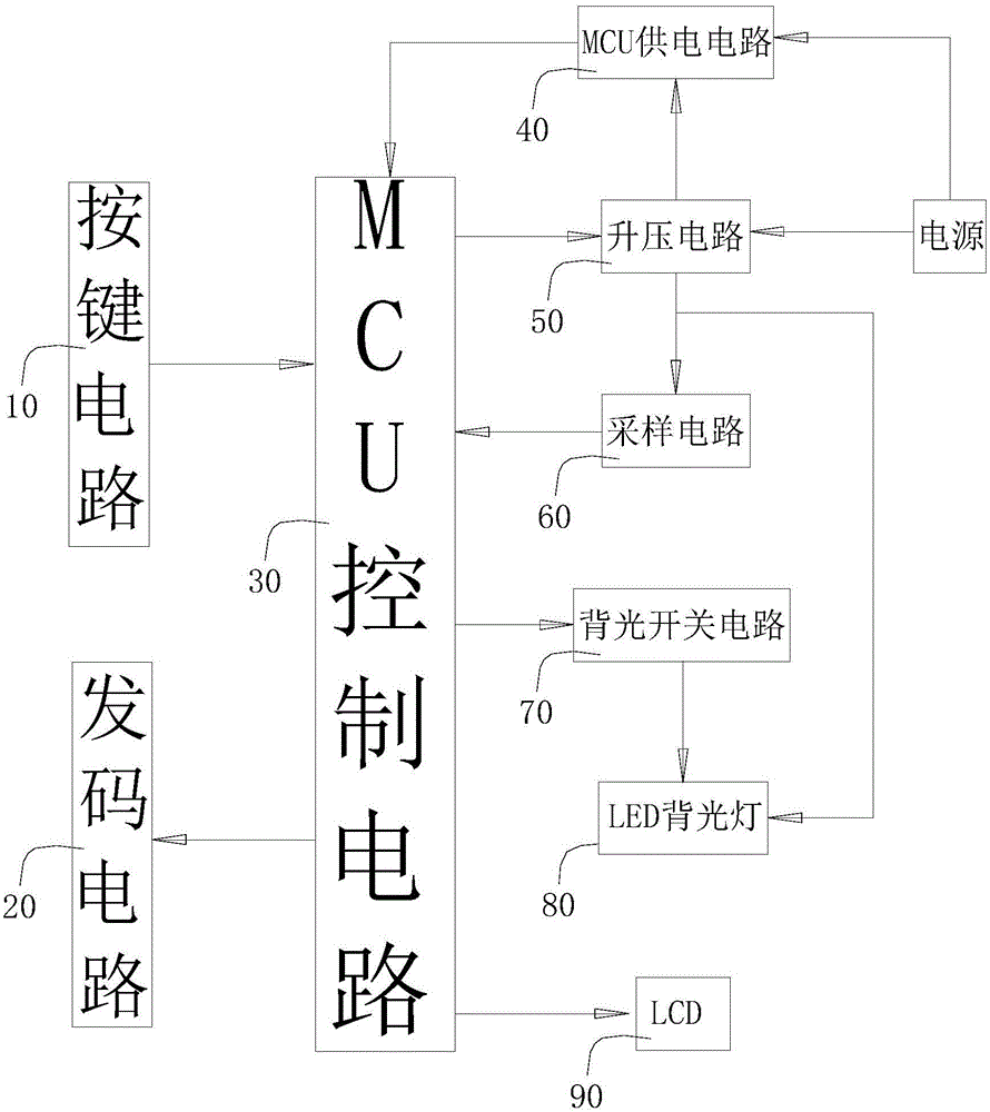
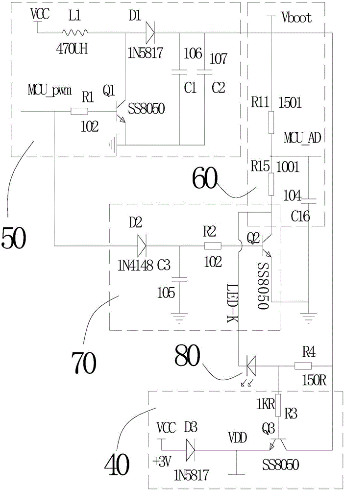
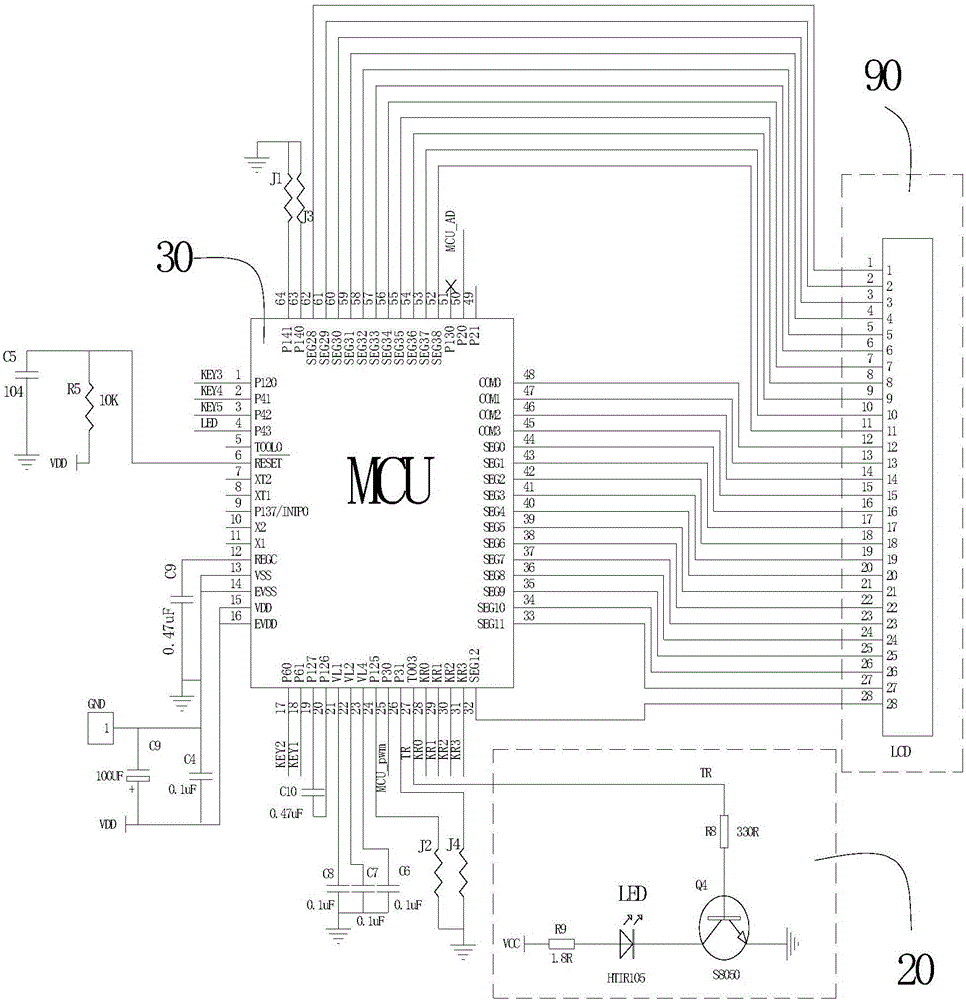
[0018] Such as figure 1 , a remote controller control circuit with a backlight screen, including a button circuit 10 for converting button manipulation into electrical signals; a code sending circuit 20 for emitting infrared signals; a power boost circuit 50 for boosting a power supply voltage VCC Output power supply to LED backlight 80, the present invention is preferably LED backlight, and other backlights with the same functional parameters are also applicable; sampling circuit 60 is used to sample the output voltage of boost circuit and output to MCU; backlight switch circuit 70, used to control the lighting and extinguishing of LED backlight 80; MCU control circuit 30, used to receive or output signals to control the above circuit and drive LCD90, and MCU power supply circuit 40, used to supply power to MCU; the button circuit 10. The code transmi...


PUM


Abstract

The invention discloses a control circuit of a remote controller with a backlight screen. The control circuit comprises a key circuit, a code sending circuit, a power supply booster circuit, a backlight switch circuit, an MCU (Microprogrammed Control Unit) control circuit and an MCU power supply circuit, wherein the power supply booster circuit is used for boosting power supply voltage and supplying power to a backlight; the backlight switch circuit is used for controlling the on and off of the backlight; the MCU control circuit is used for receiving or outputting a signal to control the circuits and driving an LCD (Liquid Crystal Display); the key circuit and the code sending circuit are connected with the MCU; the input end of the booster circuit is connected with a power supply; the output end of the booster circuit is connected with the backlight; the control end of the backlight switch circuit is connected with the MCU; the input end of the MCU power supply circuit is connected with the power supply; the output end of the MCU power supply circuit is connected with the MCU. The control circuit is characterized in that the booster circuit is also connected with the MCU; output voltage of the booster circuit is controlled by a PWM (Pulse-Width Modulation) signal outputted by the MCU. The invention provides the control circuit of the remote controller with the backlight screen. The booster circuit is used to replace a DC (Direct Current) / DC booster power supply chip, the problem of automatic reset of the remote controller is solved, and the service life of a battery is longer.

Description

technical field [0001] The invention relates to a remote controller, in particular to a remote controller control circuit with a backlight screen. Background technique [0002] Most of the remote controllers with backlit screens on the market currently use backlights with a driving voltage above 2.4V, such as white backlights; their control circuits require a DC / DC boost power chip to boost the voltage to achieve power generation. Bright screen function when coding, but the cost of the DC / DC boost power supply chip is relatively high, and in use, there is an automatic reset phenomenon and the battery life is not long enough, which affects the competitiveness of the product market. Contents of the invention [0003] In order to overcome the deficiencies of the prior art, the object of the present invention is to provide a remote controller control circuit with a backlight screen, which uses a boost circuit without an integrated chip instead of a DC / DC boost power supply chi...

Claims


Application Information

Patent Timeline
Patent Type & Authority Applications(China)
IPC IPC(8): G05B19/042
CPCG05B19/0423G05B2219/25257
Inventor 黄小茂
Owner 北京意同创科技有限公司
Learn More