
Device for improving gas energy of light gas gun by using microwave

A light gas cannon and gas technology, which is applied to weapons without explosives, electromagnetic launchers, offensive equipment, etc., can solve the problems of increasing system security, restricting the use efficiency of light gas cannons, and requiring too high pressure resistance , to achieve the effect of reducing time spent, low additional quality, and reducing time cost

Active Publication Date: 2017-01-25
XIAN INSTITUE OF SPACE RADIO TECH
View PDF5 Cites 2 Cited by
  • Summary
  • Abstract
  • Description
  • Claims
  • Application Information

AI Technical Summary

Problems solved by technology

[0006] 1. The pressure resistance of the external gas storage equipment is too high, and the gas chamber of the traditional light gas gun has no self-enhancing mechanism. Therefore, the external gas storage equipment must meet the ultra-high pressure to ensure the continuous inflation of the gas chamber and complete the projectile. Therefore, the requirements for the pressure resistance of external gas storage equipment are extremely strict, which greatly increases the hidden danger of system safety
[0007] 2. The inflation time is continuously extended. After several blows, as the pressure of the gas cylinder decreases, the time for a single inflation continues to increase, which seriously restricts the use efficiency of the light gas gun
[0008] 3. The energy utilization rate is low. The traditional light gas cannon launch system only utilizes the energy inside the external gas storage system, and the air chamber components fail to convert other forms of energy into launch power. The single method causes energy utilization. lower

Method used


Image

  • Device for improving gas energy of light gas gun by using microwave
  • Device for improving gas energy of light gas gun by using microwave
  • Device for improving gas energy of light gas gun by using microwave

Examples


Embodiment Construction

[0036] The present invention will be further described below in conjunction with accompanying drawing description and specific embodiment:

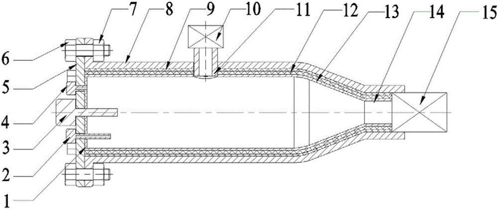
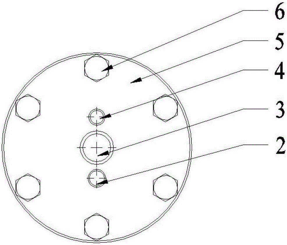
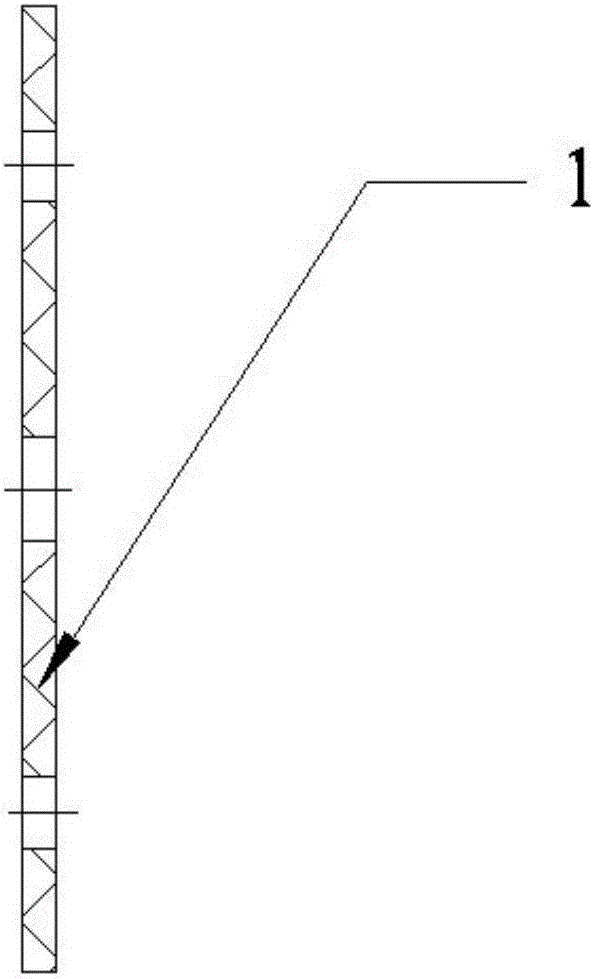
[0037] like Figure 1-6 As shown, a device that uses microwaves to increase the gas energy of a light gas gun includes a first coating 1, a microwave source 3, a flange 5, a structural layer 8, a second coating 9, an inflation interface 11, a coating base 12, The wave-absorbing layer 13 and the deflation interface 14; the structural layer 8 adopts a hollow cylinder structure, and one end of the structural layer 8 is fixedly connected with the flange 5, and the first coating 1 for heat preservation is pasted on the flange 5, and the flange Both the plate 5 and the first coating 1 are provided with holes for installing the microwave source 3, the inner side of the structural layer 8 is transitionally matched with one side of the second coating 9, and the other side of the second coating 9 is glued to the side of the coating layer 12. The o...


PUM


Abstract

The invention discloses a device for improving the gas energy of a light gas gun by a microwave, comprising a first coating layer, a microwave source, a flange, a structural layer, a second coating layer, an inflation interface, a cladding layer, a heat absorbing layer and a deflated layer, wherein the structure layer is a hollow structure and is fixedly connected with the flange; the first coating is applied on the flange, the flange and the first coating are provided with holes for installing the microwave source, the inside of the structure layer and the second coating layer have the transition fit, the other side of the second coating layer is bonded to the side of the base layer, the other side of the base layer is coated with a wave absorbing layer, a structural layer, a second coating layer, a cladding layer and a groove on the wave absorbing layer with a inflatable interface and a deflated interface which are mounted with a gas filling valve and a bleed air valve respectively to form a closed cavity. The device is characterized in that the microwave source and the absorbing layer are arranged to reach the effect of a rapid improvement of the internal pressure of the sealed chamber, makes up for the traditional light gas gun gas emission device's defects of low energy efficiency.

Description

technical field [0001] The invention relates to a device for increasing the gas energy of a light gas cannon by using microwaves, especially suitable for an ultra-high-speed kinetic energy weapon that uses microwave electromagnetic energy to rapidly enhance gas energy, and belongs to the technical field of optimization and enhancement of the light gas cannon launch system. Background technique [0002] In recent years, the research on space debris that seriously threatens the survival of space vehicles and the research on the damage effect of ultra-high-speed kinetic energy weapons have greatly promoted the rapid development of material dynamics research. As an effective means of achieving ultra-high-speed projectile launch, light gas gun Under the background of this demand, it develops and applies rapidly. [0003] Light gas cannon is a launch system widely used in high-speed impact tests. It is used in simulating space debris impact effects tests and carrying out ultra-hig...

Claims


Application Information

Patent Timeline
IPC IPC(8): F41B6/00
CPCF41B6/00
Inventor 董玉财龚利鸣孙静朱鹏
Owner XIAN INSTITUE OF SPACE RADIO TECH
Learn More