Eureka AIR delivers breakthrough ideas for toughest innovation challenges, trusted by R&D personnel around the world.

Oil way locking device

A technology of locking device and oil circuit, which is applied in the direction of fluid pressure actuating device, etc., can solve the problems of unsatisfactory oil circuit locking effect and complicated structure, and achieve the effect of good locking effect, simple operation and simple structure

Active Publication Date: 2017-01-25
浙江台意德塑机制造有限公司
View PDF10 Cites 0 Cited by
  • Summary
  • Abstract
  • Description
  • Claims
  • Application Information

AI Technical Summary

Problems solved by technology

However, the structure of the device is complicated, and the locking effect of the oil circuit is not ideal, so the structure of the device needs to be further improved

Method used


Image

  • Oil way locking device
  • Oil way locking device
  • Oil way locking device

Examples


Embodiment Construction

[0023] The present invention will be further described in detail below in conjunction with the accompanying drawings and embodiments.

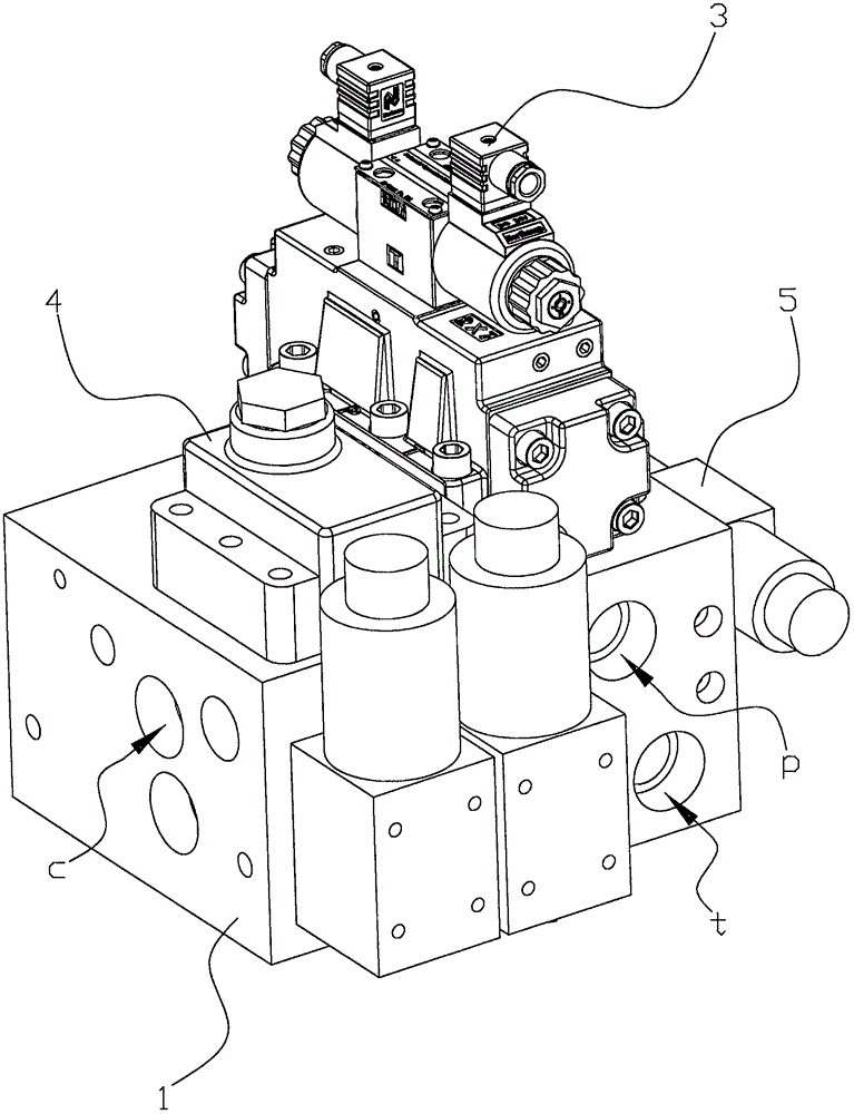
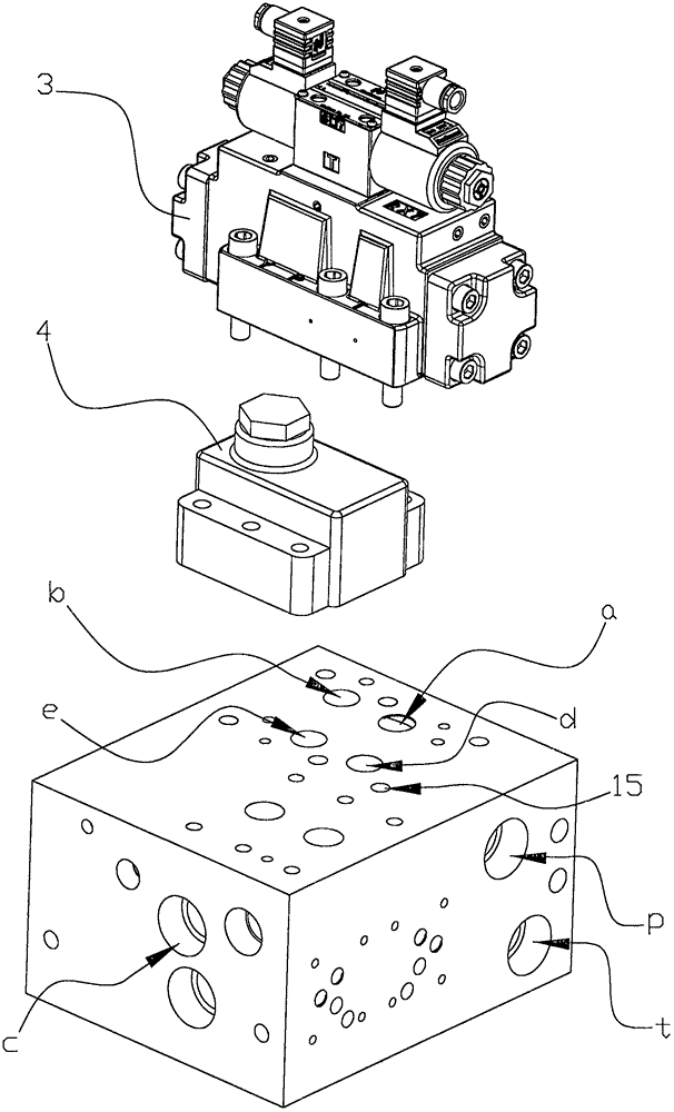
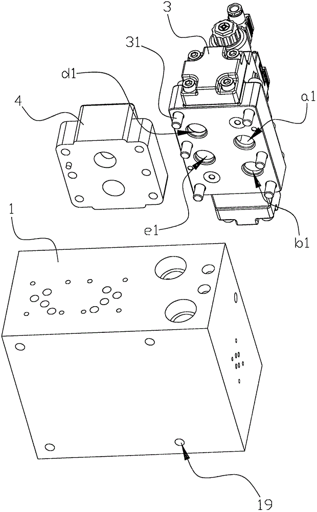
[0024] Such as Figure 1 to Figure 8 As shown, the oil circuit locking device of this embodiment includes a locking device body 1, and the locking device body 1 is provided with an oil inlet p and an oil outlet t communicated with the fuel tank, and communicated with the forward cavity of the oil cylinder 2. The oil inlet port f, the oil return port c connected to the retreat chamber of the oil cylinder 2, the reversing valve 3 and the one-way valve 4, the reversing valve 3 and the one-way valve 4 are respectively connected to the control circuit through wires, The oil inlet p, the oil outlet t, the oil inlet f and the oil return port c are respectively connected to the reversing valve 3 through pipelines, and the check valve 4 is arranged at the oil return port c to communicate with the reversing valve 3 On the pipeline, the reversing valve ...


PUM


Abstract

Provided is an oil way locking device which comprises a locking device body. The locking device body is provided with an oil inlet, an oil outlet, an oil entrance, an oil returning hole communicated with the back cavity of the oil cylinder, a directional valve and a check valve, both of which are connected with the control circuit by control cables. The oil inlet, oil outlet, oil entrance and the oil returning hole are all communicated with the directional valve. The check valve is provided at the pipe section from the oil returning valve to the directional valve. The directional valve inside is provided with a valve element moving leftward and rightward. The oil inlet and the oil returning hole are communicated. The advantages of the present device is the attainment of the opening and closing operation of the oil tank membrane, excellent locking effects, easy unlocking procedure, high efficiency; the motor control of the directional valve and the check valve with high reaction sensitivity, fast start up; solid locking device body, pipe cavities installed on the solid body communicating with various openings, simple structure and easy processing.

Description

technical field [0001] The invention relates to the technical field of hydraulic drive, in particular to an oil circuit locking device used on a hydraulic drive machine. Background technique [0002] A Chinese utility model patent whose patent number is CN200820186385.5 titled "Oil Circuit Locking Device of Hydraulic Push Rod Cylinder" discloses an oil circuit locking device of hydraulic push rod cylinder. The utility model relates to a device for locking the oil circuit of a hydraulic cylinder, in particular to an oil circuit locking device for a hydraulic push rod. The oil circuit locking device of the hydraulic push rod cylinder is adopted to improve the matching precision of the two by reducing the assembly connection between the valve core and the valve hole. Including the valve body, the oil port screw sleeve connected to the two chambers of the oil cylinder respectively, the valve body is provided with four connection ports connected with the hydraulic oil circuit, t...

Claims


Application Information

Patent Timeline
IPC IPC(8): F15B15/26
CPCF15B15/26F15B2015/268
Inventor 孙吉
Owner 浙江台意德塑机制造有限公司
Why Eureka
Eureka Blog
Learn More