Grain unloading device with augers

A grain unloading device and auger technology, applied in the field of granary structure design, can solve problems such as single function, high cost, and large area occupation, and achieve the effect of compact and simplified structure, low cost and reasonable structure

Pending Publication Date: 2017-01-25
SUZHOU JUNFENGCHEN ELECTRONICS TECH
View PDF6 Cites 0 Cited by
  • Summary
  • Abstract
  • Description
  • Claims
  • Application Information

AI Technical Summary

Problems solved by technology

[0003] At present, most of the traditional granaries adopt a single-body design, which can only store one kind of grain at the same time, and has a single function
There are also some granaries that adopt a double-body design, but use two separate sets of unloading devices to unload grain separately, resulting in the disadvantages of occupying a large area and high cost

Method used


Image

  • Grain unloading device with augers
  • Grain unloading device with augers
  • Grain unloading device with augers

Examples


Embodiment 1

[0036] (Embodiment 1, grain unloading device)

[0037] Figure 1 to Figure 6 A first embodiment of the invention is shown.

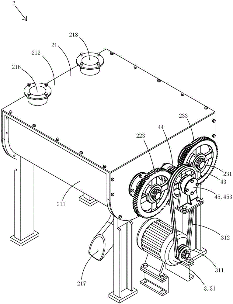
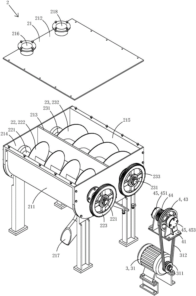
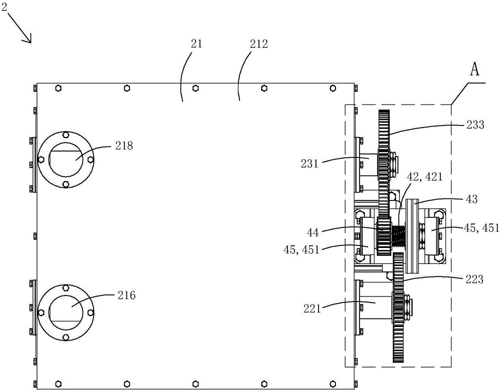
[0038] This embodiment is a grain unloading device with an auger, see Figure 1 to Figure 6 As shown, the grain unloading device 2 includes a box body 21, a first auger 22, a second auger 23 and a driving device 3 for driving the first auger and the second auger to rotate.

[0039] Casing comprises base 211 and cover 212, is provided with dividing plate 213 in the base, and dividing plate is divided into the first grain unloading cavity 214 of equal size and the second unloading cavity 215 of equal size by dividing plate; A first grain inlet 216 connected to the grain unloading chamber, the bottom of the first grain unloading chamber is provided with a first grain outlet 217; the cover is also provided with a second grain inlet 218 connected to the second grain unloading chamber, The bottom of the second grain unloading cavity is provided with a secon...

Embodiment 2

[0054] (Example 2, grain unloading device)

[0055] Figure 7 to Figure 11 A second embodiment of the invention is shown.

[0056] This embodiment is basically the same as Embodiment 1, the difference is: see Figure 7 to Figure 11 As shown, the side end of the limit block in this embodiment is closer to the pulley, the side end of the pulley closer to the limit block, and both sides of the clutch transmission gear are provided with gear teeth 5, Each tooth is provided with a thrust surface 51 and a guide surface 52, and each guide surface is an arc surface. When the clutch transmission gear translates towards the direction of the limit stop, the thrust surface of the gear teeth of the clutch transmission gear finally abuts against the thrust surface of the gear teeth of the limit stop; when the clutch transmission gear translates towards the direction of the pulley, the clutch The thrust bearing surface of the gear teeth of the transmission gear finally abuts against the t...


PUM


Abstract

The invention discloses a grain unloading device with augers. The grain unloading device with the augers comprises a box body, a first auger, a second auger and a driving device, wherein the box body is provided with a first grain unloading cavity and a second grain unloading cavity; the first auger is used for unloading grain stored in the first grain unloading cavity; the second auger is used for unloading grain stored in the second grain unloading cavity; the driving device is used for driving the first auger and the second auger to rotate; the first auger comprises a first rotating shaft, a first spiral plate and a first driven gear; the second auger comprises a second rotating shaft, a second spiral plate and a second driven gear; the driving device comprises a driving motor and a clutch linkage device; the clutch linkage device comprises a frame body, a driving shaft, a clutch driving gear and a belt wheel; the driving shaft is provided with an external thread part; the clutch driving gear is spirally connected with the external thread part of the driving shaft; and the clutch driving gear is positioned at a first driving station when moving to one end of the external thread part, and is positioned at a second driving station when moving to the other end of the external thread part. The grain unloading device with the augers is compact and reasonable in structure.

Description

technical field [0001] The invention belongs to the technical field of granary structure design, and in particular relates to a grain unloading device with an auger. Background technique [0002] The food problem is one of the urgent problems that attract worldwide attention. my country, as the most populous country in the world, consumes a large amount of food every year. Only with food can a country develop industry, national defense, service industry, scientific and cultural undertakings in a stable and healthy manner. The food issue is not only an economic and people's livelihood issue, but also a development and security issue. With the rapid development of green food and the continuous improvement of people's living standards, green grain storage technology has made great progress in our country. Under the guidance of "China's Grain Storage Ecosystem Theory System", my country's grain storage concept is undergoing profound changes. Grain storage technology is developi...

Claims


Application Information

Patent Timeline
Patent Type & Authority Applications(China)
IPC IPC(8): B65G65/46
CPCB65G65/46
Inventor 申俊
Owner SUZHOU JUNFENGCHEN ELECTRONICS TECH
Why Eureka
Try Eureka