
Milling cutter for processing

A milling cutter and body technology, applied in milling cutters, metal processing equipment, manufacturing tools, etc., can solve the problems of relative position deviation, shaking, insufficient stability of the base and the milling cutter body, etc., and achieve a stable and reliable connection

Inactive Publication Date: 2017-01-25
SUZHOU LINGYU ELECTRONICS TECH CO LTD
View PDF8 Cites 0 Cited by
  • Summary
  • Abstract
  • Description
  • Claims
  • Application Information

AI Technical Summary

Problems solved by technology

[0002] For existing milling cutters, the base of the milling cutter body is generally only connected by bolts. The stability between the base and the milling cutter body is not enough. After a long time of use, it will shake and the relative position will deviate.

Method used


Image

  • Milling cutter for processing

Examples


Embodiment Construction

[0012] The specific implementation manners of the present invention will be further described below in conjunction with the drawings and examples. The following examples are only used to illustrate the technical solutions of the present invention more clearly, but not to limit the protection scope of the present invention.

[0013] The technical scheme of concrete implementation of the present invention is:

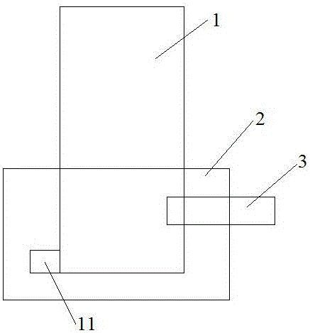
[0014] Such as figure 1 As shown, a milling cutter for processing includes a milling cutter body 1 and a base 2. The milling cutter body 1 is cylindrical, and the front end of the milling cutter body 1 is provided with two cutting edges. The cutting surface is flat, and chip removal grooves are formed between the corresponding cutting surfaces of the two cutting edges. The milling cutter body 1 is arranged vertically. The side wall of the knife body 1, the above-mentioned base 2 are arranged horizontally, the above-mentioned base 2 is provided with a cylindrical mountin...


PUM


Abstract

The invention discloses a milling cutter for processing. The milling cutter comprises a milling cutter body and a base, wherein two cutting blades are arranged at the front end of the milling cutter body; a limiting block is arranged at the rear end of the milling cutter body; a columnar mounting hole is formed in the base; the mounting hole is formed vertically; a connecting groove is formed in the inner wall of the mounting hole; the connecting groove is formed vertically, and is connected with a limiting groove; the limiting groove is horizontally formed; the rear end of the milling cutter body is arranged inside the mounting hole; the limiting block is arranged inside the limiting groove; a first threaded hole is formed in the side wall of the mounting hole; a second threaded hole is formed in the milling cutter body; a second threaded hole is formed in the milling cutter body; the first threaded hole is connected with the second threaded hole through a bolt. The milling cutter has the beneficial effect that the milling cutter body can be stably and reliably connected with the base.

Description

technical field [0001] The invention relates to a milling cutter for machining. Background technique [0002] In the existing milling cutters, the milling cutter body and the base are generally only connected by bolts, and the stability between the base and the milling cutter body is not enough. After a long time of use, shaking will occur and the relative position will deviate. Contents of the invention [0003] The object of the present invention is to provide a milling cutter for machining, the connection between the milling cutter body and the base is stable and reliable. [0004] To achieve the above object, the present invention provides the following technical solutions: [0005] A milling cutter for machining, comprising a milling cutter body and a base, the milling cutter body is cylindrical, the front end of the milling cutter body is provided with two cutting edges, the cutting surfaces of the two cutting edges are plane, and the two Chip flutes are formed bet...

Claims


Application Information

Patent Timeline
IPC IPC(8): B23C5/16
CPCB23C5/16
Inventor 夏亮明
Owner SUZHOU LINGYU ELECTRONICS TECH CO LTD
Learn More