
Dedusting equipment

A technology of equipment and filter cartridges, which is applied in the field of dust removal equipment, can solve the problems of reduced fan efficiency, high wind pressure in local cavities, and high wind noise, etc., and achieve the effect of improving filtration efficiency, good noise reduction effect, and good noise reduction effect

Inactive Publication Date: 2017-01-18
倪静
View PDF8 Cites 3 Cited by
  • Summary
  • Abstract
  • Description
  • Claims
  • Application Information

AI Technical Summary

Problems solved by technology

[0002] In the existing air purification equipment, the fan is generally installed at the air outlet of the equipment. This structure has the following disadvantages: the noise of the motor running is directly transmitted to the external environment. In order to reduce noise, a muffler must be installed at the equipment outlet; the fan generally All are equipped with a volute, which will inevitably lead to excessive wind pressure in the local cavity, which will reduce the efficiency of the fan; the wind speed at the air outlet section is uneven, and the local excessive wind speed will generate a lot of wind noise. At the same time, the wind speed distribution is uneven. Uniformity will lead to a decrease in the utilization rate of the air duct, so a larger diameter air duct is required
However, the overall layout of the air purification equipment determines that it has problems such as high noise, low utilization rate of the air duct, and limited dust removal effect.

Method used


Image

  • Dedusting equipment
  • Dedusting equipment
  • Dedusting equipment

Examples


Embodiment 1

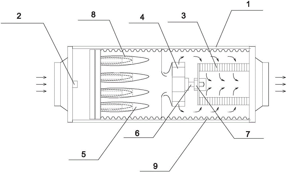
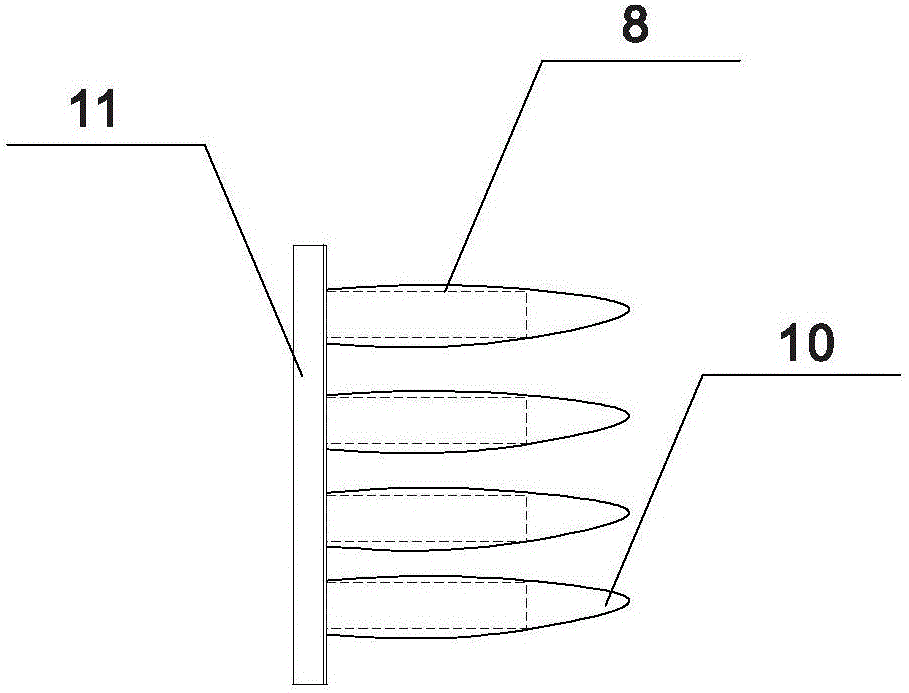
[0028] like figure 1 , figure 2 As shown, a dust removal device includes a square cylindrical box body 1, the axis of the box body 1 is horizontal, the inlet end of the box body 1 is provided with a negative ion generator 2, and the outlet end of the box body 1 is provided with a filter with a closed end. Cartridge 3, the wall of the filter cartridge 3 is surrounded by a filter screen, the end face of the opening end of the filter cartridge 3 is sealed and bonded to the end wall of the outlet end of the box body 1, and the opening of the filter cartridge 3 is connected to the outlet of the box body 1, and the negative ions An intermediate filter device is provided between the generator 2 and the filter cartridge 3, and a fan 4 is fixed between the intermediate filter device and the filter cartridge 3, and the fan 4 is fixed on a fan fixing frame arranged along the cross section of the box body 1. The axes of the filter cartridge 3 , the fan 4 and the box body 1 are coinciden...

Embodiment 2

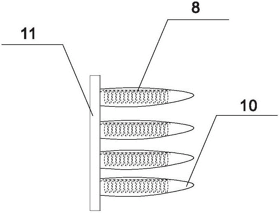
[0031] like image 3 As shown, the inside of the bag filter of the bag filter 5 is provided with an expansion support frame 8, which is a deformable helical structure and is made of elastic strip material, which is a spring steel wire in this embodiment. The upper edge of the air hole of the bag filter 5 filter screen support is also fixed with an axially protruding pick rod, and the pick rod penetrates into the center hole of the spiral coil of the expansion support frame 8, which can prevent the expansion support frame 8 from being damaged by the bag-shaped filter screen. The radial bending is generated due to the gravity falling, so as to maintain the shape and movement function of the expansion support frame 8. All the other are with embodiment 1.

[0032] The expansion support frame 8 can not only expand the bag filter 5, but also has a buffering effect like a spring. When the wind speed in the box 1 is unstable, the bag filter 5 can be used to disturb the flow in the ai...

Embodiment 3

[0034] The intermediate filtering device is a finishing structure, and the expansion support frame 8 is cylindrical. All the other are with embodiment 1.


PUM


Abstract

The invention discloses dedusting equipment. The dedusting equipment comprises a box body, wherein a negative ion generator is arranged at the inlet end of the box body, a filter cartridge which is closed at one end is arranged at the outlet end in the box body, a filter screen is arranged around the wall of the filter cartridge, the end surface of the opened end of the filter cartridge is hermetically attached to the end wall of the outlet end of the box body, the opening of the filter cartridge communicates with the outlet of the box body, a fan is fixedly arranged between the negative ion generator and the filter cartridge, the fan and the filter cartridge are coaxial, and the closing end of the filter cartridge props against the fan. The dedusting equipment disclosed by the invention is better in noise reducing effect and more thorough to dedust, and the work efficiency of the fan and the utilization ratio of an air duct are improved.

Description

technical field [0001] The present invention relates to an air purification device, more specifically, it relates to a dust removal device. Background technique [0002] In the existing air purification equipment, the fan is generally installed at the air outlet of the equipment. This structure has the following disadvantages: the noise of the motor running is directly transmitted to the external environment. In order to reduce noise, a muffler must be installed at the equipment outlet; the fan generally All are equipped with a volute, which will inevitably lead to excessive wind pressure in the local cavity, which will reduce the efficiency of the fan; the wind speed at the air outlet section is uneven, and the local excessive wind speed will generate a lot of wind noise. At the same time, the wind speed distribution is uneven. Uniformity will lead to a decrease in the utilization rate of the air duct, so a larger diameter air duct is required. [0003] In some air purific...

Claims


Application Information

Patent Timeline
Patent Type & Authority Applications(China)
IPC IPC(8): F24F1/02F24F13/24F24F13/28B03C3/017
CPCF24F13/24F24F13/28F24F2013/242F24F8/192
Inventor 倪静
Owner 倪静
Learn More